7 ground connector, 8 if in (j4, buc-4000 only), 9 comm (j6, buc-/bdc-4000) – Comtech EF Data MBT-4000 User Manual
Page 33
MBT-4000 Multi-Band Transceiver System
Revision 4
External Connectors
MN/MBT4000.IOM
3–7
3.2.1.7 Ground Connector
A #10-32 stud is used for connecting a common chassis ground among equipment.
3.2.1.8 IF IN (J4, BUC-4000 ONLY)
The J4 IF IN connector, located on the BUC-4000 Block Up Converter Module, is
a Type ‘N’ female connector, used to provide the IF Input signal for the
upconverter.
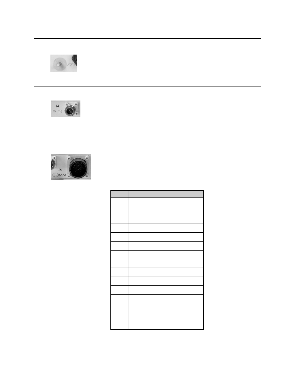
3.2.1.9 COMM (J6, BUC-/BDC-4000)
The J6 COMM connector, featured on both the BUC-4000 Block Up
Converter and BDC-4000 Block Down Converter Modules, is used for
connecting the module to the MBT-4000 Base Module J3 UNIT 1 COMM
or J6 UNIT 2 COMM connectors via the 15-15 Power & Signal Harness
(CEFD P/N CA/WR10963-1), as shown in Figure 3-2 and Figure 3-3.
Table 3-7. UNIT 2 COMM (J6) Connector Pinouts
Pin
Signal
A SUM
FLT
B TxD
BXC
C Tx+
BXC
D GND
E +7.5V
F +7.5V
G +15V
H GND
J Rx+
BXC
K Rx-
BXC
L Tx-
BXC
M RxD
BXC
N SPARE
P
10 MHz REF
R SPARE
NOTE – Mating Connector:
CEFD P/N CN/8LT5-15B15SN