3 common features, 4 options – Comtech EF Data MBT-4000 User Manual
Page 20
MBT-4000 Multi-Band Transceiver System
Revision 4
Introduction
MN/MBT4000.IOM
1–2
From
Modem
To
Modem
70 MHz
To C-Band HPA
From C-Band LNA
M&C
IF In
Ref In
Ref In
IF Out
IF Out
IF In
RF Out
RF In
RF In
RF In
M&C
M&C
Ref In
IF Out
IF Out
L-Band
Splitter
LBC-4000
LBC-4000
IDU
70 MHz
To
Modem
To
Modem
70 MHz
70 MHz
L-Band
L-Band
L-Band
L-Band
5 MHz
RS-485
RS-485
RS-485
5 MHz
5 MHz
BUC-4000C
BDC-4000C
Multi-Band Transceiver
RF Out
RF IN
• System status verification via LEDs located behind a removable cover
• Flexible configuration:
2 Ups
2 Downs
1Up / 1 Down
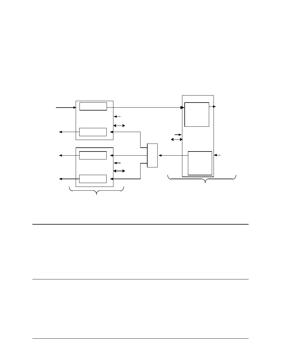
Figure 1-2 depicts the operation schematic for a typical MBT-4000 application.
Figure 1-2. MBT-4000 Operational Schematic
1.3
Common Features
• Meets or exceeds MIL-STD-188-164A
• Low phase noise
• Auto band sensing capability
• Functions in 1 MHz step sizes
1.4
Options
• Functions in 1 kHz step sizes
• Dual-Base (Chain) Redundancy Operation (see Figure 1-3)
- CDD-880 (124 pages)
- CDM-800 (130 pages)
- ODMR-840 (184 pages)
- CDM-750 (302 pages)
- CDM-840 (244 pages)
- SLM-5650A (420 pages)
- CTOG-250 (236 pages)
- CDM-700 (256 pages)
- CDM-760 (416 pages)
- CDM-710G (246 pages)
- CDM-600/600L (278 pages)
- CDMR-570L (512 pages)
- CDM-625 (684 pages)
- CDM-625A (756 pages)
- CDD-564A (240 pages)
- CDD-564L (254 pages)
- CLO-10 (134 pages)
- MCED-100 (96 pages)
- CDMR-570AL (618 pages)
- CDM-600 LDPC (2 pages)
- BUC Power Supply Ground Cable (2 pages)
- MPP70 Hardware Kit for CDM-570L (4 pages)
- MPP50 Hardware Kit for CDM-570L (4 pages)
- CDM-625 DC-AC Conversion (4 pages)
- CDM-625 DC-AC Conversion with IP Packet Processor (4 pages)
- DMDVR20 LBST Rev 1.1 (117 pages)
- DMD2050E (212 pages)
- DMD-2050 (342 pages)
- DMD1050 (188 pages)
- OM20 (220 pages)
- QAM256 (87 pages)
- DD240XR Rev Е (121 pages)
- MM200 ASI Field (5 pages)
- DM240-DVB (196 pages)
- MM200 (192 pages)
- CRS-150 (78 pages)
- CRS-280L (64 pages)
- CRS-170A (172 pages)
- CRS-180 (136 pages)
- SMS-301 (124 pages)
- CiM-25/8000 (186 pages)
- CiM-25 (26 pages)
- CRS-500 (218 pages)
- CRS-311 (196 pages)
- CIC-20 LVDS to HSSI (26 pages)