5 monitoring operations via the led indicators – Comtech EF Data MBT-4000 User Manual
Page 38
MBT-4000 Multi-Band Transceiver System
Revision 4
System Operating Parameters
MN/MBT4000.IOM
4–2
4.4
Block Down Converter Module (BDC-4000) Operating Parameters
The BDC-4000 translates a band-specific input frequency block (C-, X-, or Ku- or Ka-Band)
from the LNA down to L-Band (950 to 2000 MHz).
Table 4-2. BDC-4000 C-, X-, KU-, and Ka-Band Operating Parameters
Band
Frequency
LO Frequency
Inverting
C-Band
3400 – 4200 MHz
5150 MHz
Yes
X-Band
7250 – 7750 MHz
6300 MHz
No
Ku-Band-W
(Single module
containing three LOs)
10.95 – 11.70 GHz
11.7 – 12.20 GHz
12.250 – 12.75 GHz
10.00 GHz
10.75 GHz
11.30 GHz
No
Ka-Band
20.20 – 21.20 GHz
Notes:
1. No spectral inversion, selectable inversion for inverted Block Down Converter.
2. 10 dB gain adjustment.
4.5
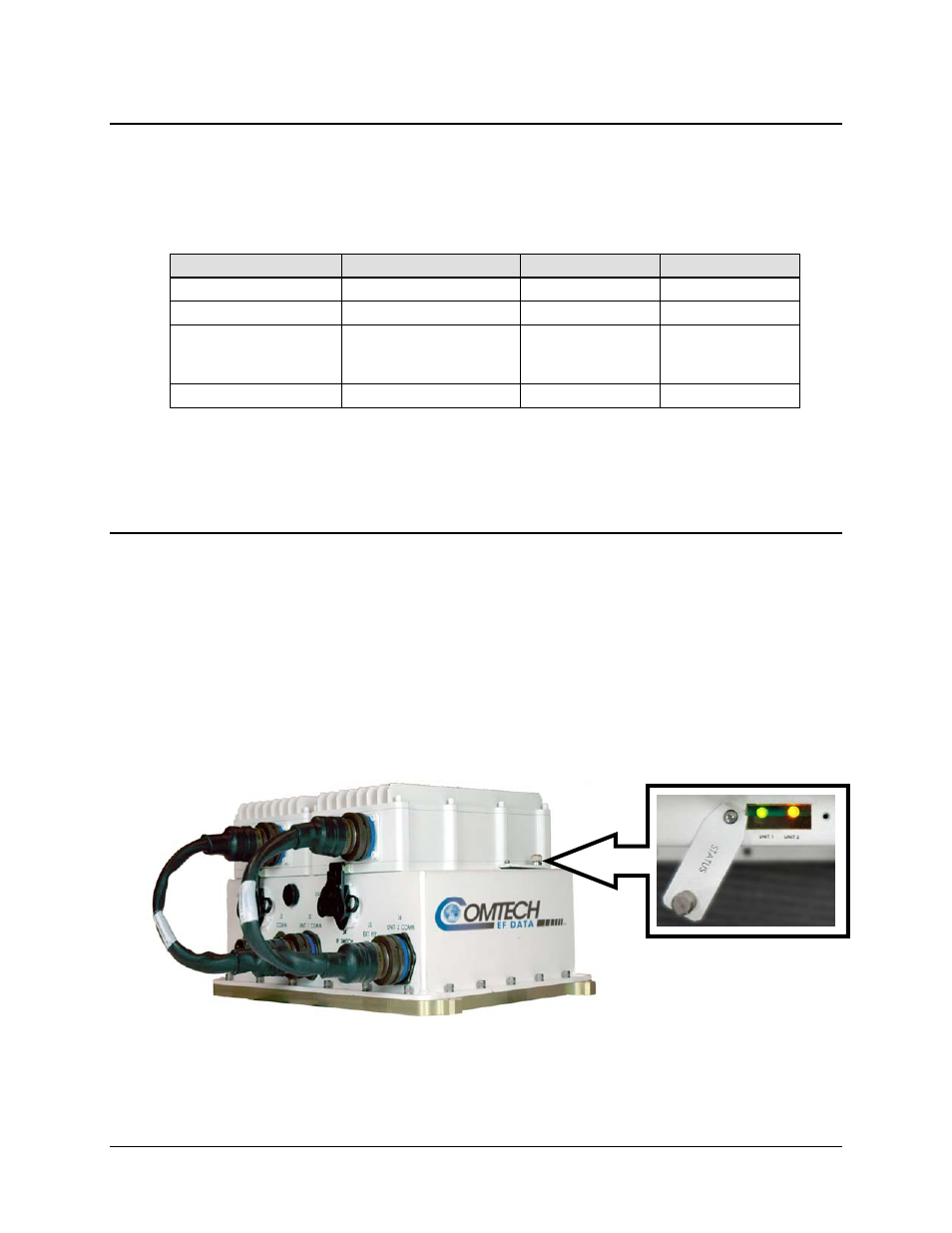
Monitoring Operations via the LED Indicators
The MBT-4000 Multi-Band Transceiver System features two Light-Emitting Diode (LED)
indicators – one for each operational unit (module). Each LED provides the user with visual cues
to the operational, online, and offline status of the sytem.
Figure 4-1 illustrates the location of the LED Indicators. Located on the top of the MBT-4000’s
Base Module under a pivoting protective plate, the LEDs may be viewed by loosening the
thumbscrew that keeps the plate in place; the user can then swing the plate away to reveal the
LED display window.
Appendix B. FAULTS/EVENTS provides complete details for interpreting the LED Indicators.
Figure 4-1. MBT-4000 Multi-Band RF Transceiver LED Indicators