AMETEK DCS-E 3kW Series User Manual
Page 80
Theory of Operation
Sorensen DCS-E Series 3kW Supplies
5-10
M362295-01 Rev C
Note: When installed and enabled, the optional IEEE-488 card has the highest priority as a
programming source and will override the selection of either local control or remote
analog programming.
In both the voltage and current control circuits, selection of the reference signal source is
controlled by two CMOS switches and a pair of associated logic gates. Switching between local
programming mode and remote analog programming can be accomplished using either the front
panel REM/LOC switch or the rear panel J3 connector. The front panel REM/LOC switch can be
used whenever operations involve programming of BOTH the output voltage AND current limit
using remote voltage sources (0-5V or 0-10V) or current sources (0-1 mA). Use of the
REM/LOC switch allows the operator to switch back and forth between local and remote analog
programming without changing any of the default J3 connections. In applications requiring the
use of resistive programming, or where programming of the output voltage AND/OR the output
current limit is necessary, the J3 connector must be used to select the programming source.
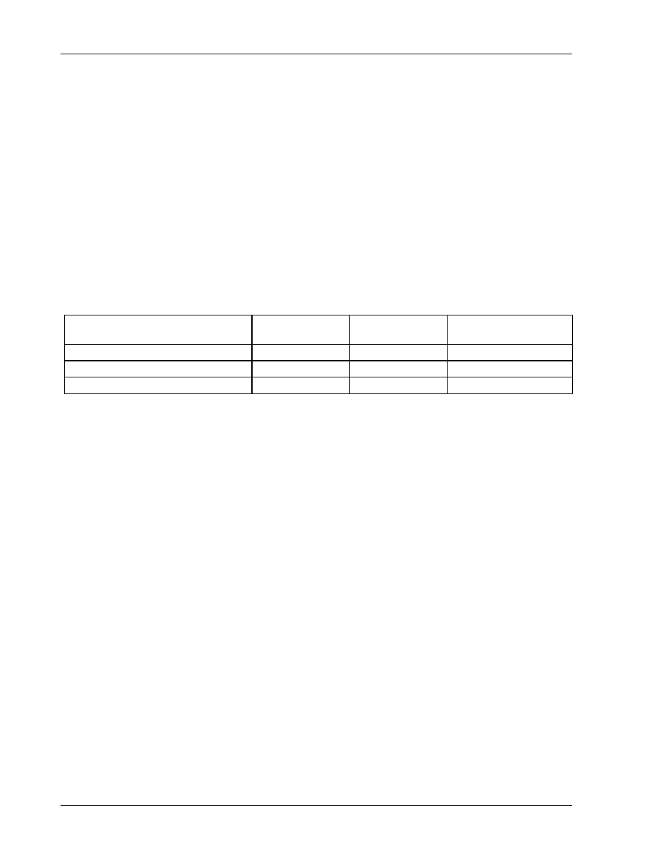
In the voltage control circuit, analog switches U4-C and U4-B select which of the three
programming sources is enabled according to the following table.
Programming Source Enabled
Switch U4-C
Switch U4-B
IEEE-488 Enable
(Pin P2-4)
Local programming
ON
OFF
HIGH
Remote analog programming
OFF
ON
HIGH
IEEE-488 programming
OFF
OFF
LOW
The analog gates are controlled by logic gates U5-D and U5-A. In local programming mode,
both inputs to U5-D are high and its output is low. Pin 12 of U5-D is held high by the J3
connector jumper connecting the 1 mA current source at pin 21 to resistor R73 while pin 13 is
held high by a +15V signal through resistors R74-R76. The low output of U5-D turns ON gate
U4-C, connecting the front panel control signal to the voltage control op amp U3-D, and turns
gate U4-B OFF by causing the output of U5-A to go high.
When remote analog programming is selected using the front panel REM/LOC switch, pin 13 of
U5-D is pulled low through diode CR12, causing the output of U5-D to go high. This shuts OFF
gate U4-C and causes the output of U5-A to go low which turns ON gate U4-B, connecting the
remote programming signal to the voltage control circuit.
When analog programming is selected using the J3 connector, the jumper connecting pins 21
and 20 is removed, disconnecting the 1 mA current source from resistor R73. Pin 12 of U5 D is
then pulled low through resistors R72 and R73, causing the output of U5-D to go high. This
turns gate U4-C OFF and gate U4-B ON, connecting the remote programming signal to U3-D.
Selection of IEEE-488 programming occurs when the IEEE card pulls pin 13 of U5-D and pin 2
of U5-A low through connector P2, pin 4. This causes the output of both U5-D and U5-A to go
high and switch OFF both U4-C and U4-B. The IEEE programming signal is then input to the
voltage control op amp through resistor R78.
Operation of the current control circuit is the same as the voltage control circuit with CMOS
switches U4-D and U4-A and NAND gates U5-B and U5-C providing the required functions.
The operation of the front panel remote indicator LED and the J3 remote programming indicator
signal is controlled by transistor Q2. Whenever either remote analog or IEEE-488 programming
is selected, the output of U5-D and/or U5-C is high. This high signal is input to the base of