4 strain relief assembly – AMETEK DCS-E 3kW Series User Manual
Page 30
Installation
Sorensen DCS-E Series 3kW Supplies
2-6
M362295-01 Rev C
C
ONTACT
I
NSTALLATION
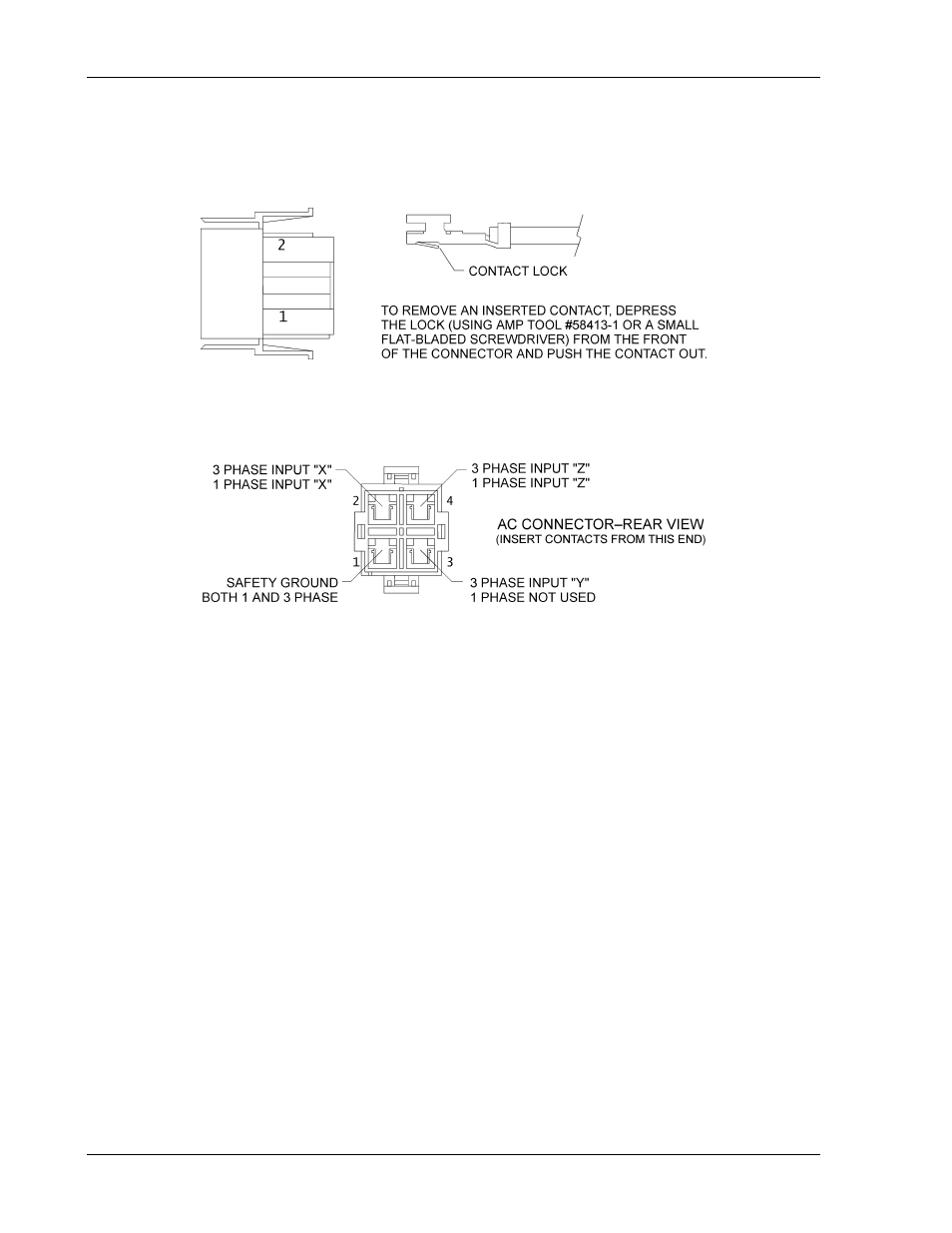
5. Insert contact with attached wire into the connector until lock snaps into place. See
Figure 2-3 and Figure 2-4 to complete the connector for either single or three phase
input.
Figure 2-3 Contact Orientation
Figure 2-4 AC Wire Locations
2.5.4
Strain Relief Assembly
The strain relief is assembled from supplied pieces and attaches to the AC input connector to
provide support for the AC input cord.
P
ARTS
S
UPPLIED
•
Two (2) pieces strain relief Part number MI-6432-661, Tyco 643266-1
•
Two (2) screws Part number MS-6PPS-10 (screw #6-32, 5/8” long, self tapping)
A
SSEMBLY
I
NSTRUCTIONS
1. Snap off the rectangular bushing attached to each piece of the strain relief.
See Figure 2-5.
2. Install bushings on strain relief pieces, if required:
If cable diameter is within 0.1" to 0.4", install bushings.
If cable diameter is within 0.5" to 0.74", do not use bushings.
- CW-M (48 pages)
- CW-M Corrected Table 4-2 in (1 page)
- CW-P (62 pages)
- Lx Series (205 pages)
- CW Series Programming Manual (25 pages)
- Ls Series II Programming Manual (242 pages)
- Compact i/iX Series (157 pages)
- Compact IX 2253 (157 pages)
- Compact i/iX Series Software Manual (203 pages)
- ASD Series Quick Start (5 pages)
- ASD Series (120 pages)
- i-iX Series II Programming Manual (226 pages)
- DLM 600W Series Programming Manual (24 pages)
- M131 Programming Manual (99 pages)
- DLM Series (74 pages)
- DLM 600W Series (82 pages)
- BPS Series (153 pages)
- DLM600 Series (16 pages)
- DCS-E 1.2kW Series (65 pages)
- DLM-E 4kW Series Programming Manual (32 pages)
- M136 (8 pages)
- CTS 3.0 (166 pages)
- CSW Series (174 pages)
- 2003RP (126 pages)
- 2001RP (131 pages)
- MX CTSH (151 pages)
- MXCTSL Administrator Manual (27 pages)
- MX CTSL (157 pages)
- RS Series (228 pages)
- MX Series Installation Manual (35 pages)
- Ls AC source (2 pages)
- MX15 Series (184 pages)
- Ls Series II (226 pages)
- Lx Series Driver Manual (275 pages)
- MX Series Rev: AY (257 pages)
- iX Series (341 pages)
- i-iX Series II (258 pages)
- GUPS 2400A-108 (36 pages)
- HPD Series (58 pages)
- HPD Series Operation Manual (41 pages)
- HPD Series GPIB-Multichannel (134 pages)
- PLA-PLW Programming Manual (74 pages)
- ReFlex Mating Connnectors for Controller (3 pages)
- LPDC-16V (4 pages)