3 programming ovp with an external voltage source – AMETEK DCS-E 3kW Series User Manual
Page 59
Sorensen DCS-E Series 3kW Supplies
Advanced Operation
M362295-01 Rev C
4-15
4.4.3
Programming OVP with an External Voltage Source
To set the OVP trip level with a 0-5 Vdc or a 0-10 Vdc external voltage source:
1. Ensure the power supply is turned OFF and that both the AC power source and the load
are disconnected. Allow five (5) minutes to elapse to dissipate stored energy before
resetting switches or making connections. Refer to Section 4.2 for instructions for
removing the cover and resetting switches or making J3 connections.
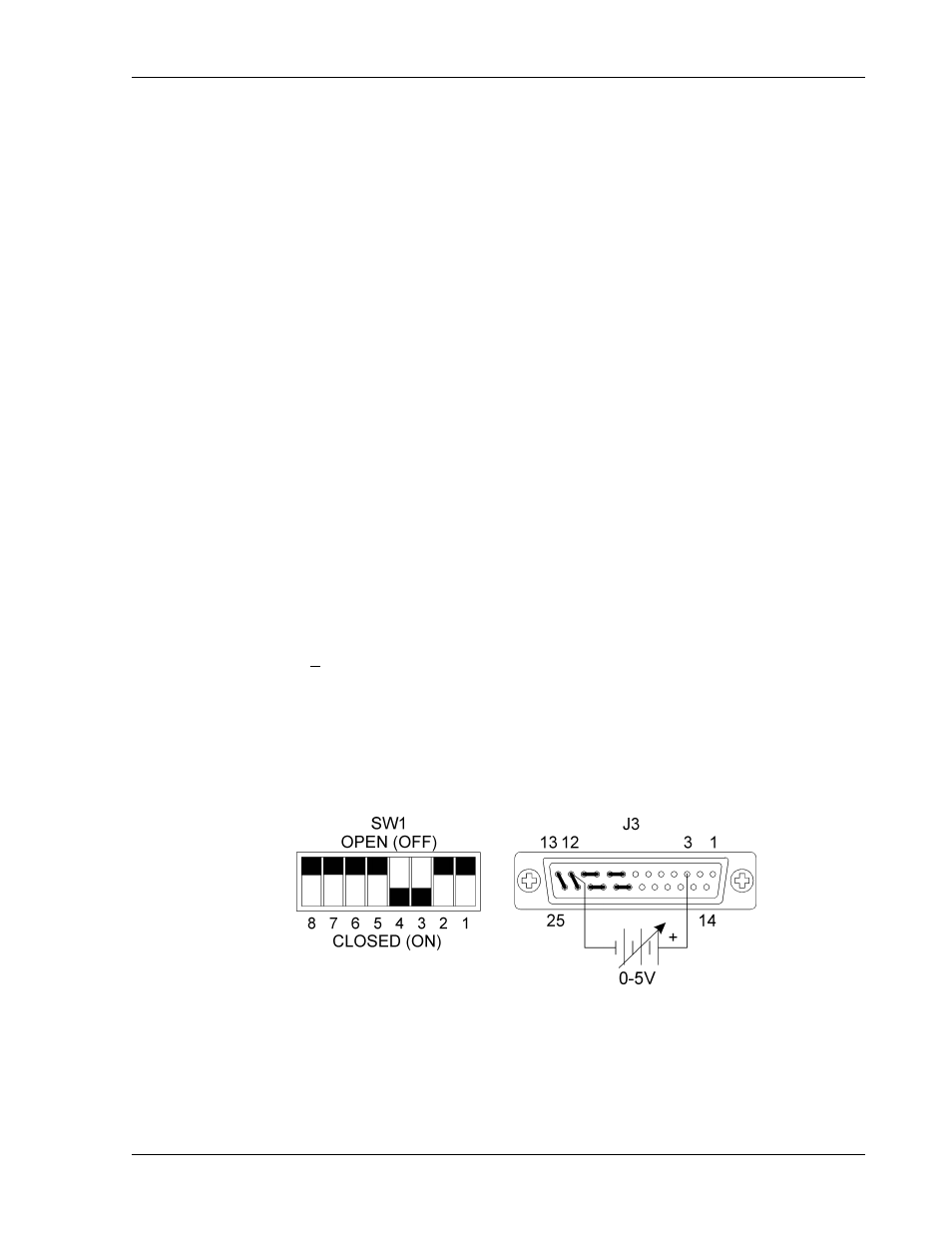
2. Set the power supply's internal switch SW1-7 OPEN. Ensure switch SW1-6 is set to
OPEN for 0-5 Vdc OVP programming (factory default setting) or set it to CLOSED for
0-10 Vdc OVP programming. See Figure 4-12 and Figure 4-13.
3. Connect the external voltage source between pin 3 (positive) and pin 12 (return) on
the J3 connector on the rear panel. See Figure 4-12 and Figure 4-13. The use of
shielded-twisted pair wiring is recommended. Ground the shield to J3 connector pin 6 or
to the chassis using one of the J3 connector screws.
4. Set the external programming source voltage to maximum (5 Vdc or 10 Vdc).
5. Turn the power supply ON and turn the front panel voltage control clockwise until the
voltmeter shows the desired trip voltage.
6. Slowly reduce the external programming voltage until the red OVP LED lights and the
power supply shuts down.
Note: When OVP is programmed by an external voltage source, the OVP set point can be
approximated using the following formula:
OVP Set Point + 2% = (V
O
/ PGM
SCALE
)V
PGM
where: V
O
is the power supply model-rated voltage
PGM
SCALE
is the external voltage source maximum voltage (5 or 10)
V
PGM
is the remote OVP program voltage setting (0 to 5 Vdc or 0 to 10 Vdc)
Figure 4-12 Remote Programming of OVP with a 0-5 Vdc External Voltage Source