AMETEK DCS-E 3kW Series User Manual
Page 61
Sorensen DCS-E Series 3kW Supplies
Advanced Operation
M362295-01 Rev C
4-17
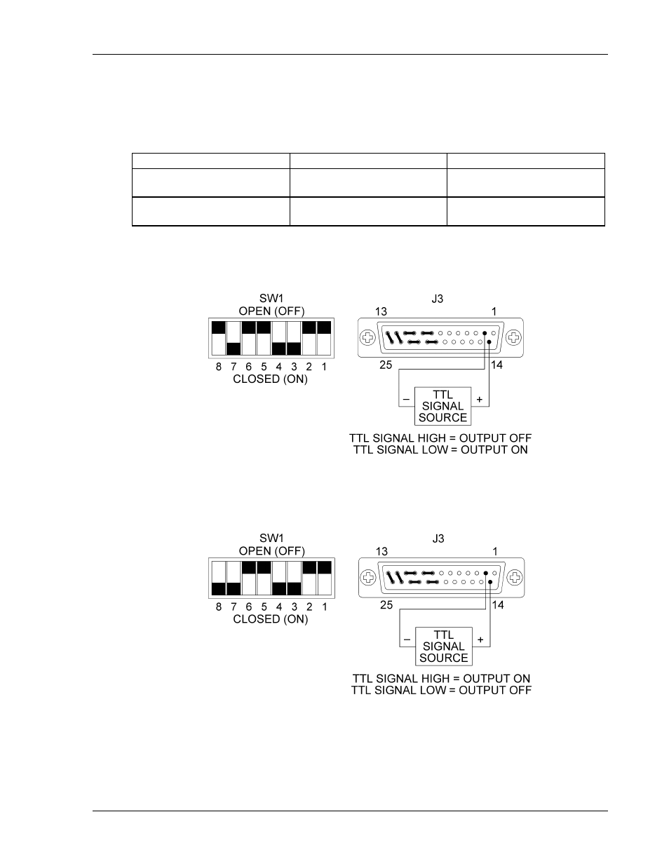
2. Connect the TTL signal source to pin 14 (TTL Shutdown Input/positive) and pin 2
(Return for Shutdown Input) on the J3 connector on the rear panel. See Figure 4-14 and
Figure 4-15.
3. Set internal switch SW1-8 to select the desired circuit logic as defined in the table below.
Switch SW1-8 Setting
TTL Signal Level
Output Condition
OPEN (Positive logic)
HIGH
OFF
LOW
ON
CLOSED (Negative logic)
HIGH
ON
LOW
OFF
The red S/D (Shutdown) LED on the front panel lights up when the Shutdown circuit is
activated.
Figure 4-14 Using Shutdown with a TTL Compatible (Positive Logic)
Figure 4-15 Using Shutdown with a TTL Compatible (Negative Logic)
See also other documents in the category AMETEK Equipment:
- CW-M (48 pages)
- CW-M Corrected Table 4-2 in (1 page)
- CW-P (62 pages)
- Lx Series (205 pages)
- CW Series Programming Manual (25 pages)
- Ls Series II Programming Manual (242 pages)
- Compact i/iX Series (157 pages)
- Compact IX 2253 (157 pages)
- Compact i/iX Series Software Manual (203 pages)
- ASD Series Quick Start (5 pages)
- ASD Series (120 pages)
- i-iX Series II Programming Manual (226 pages)
- DLM 600W Series Programming Manual (24 pages)
- M131 Programming Manual (99 pages)
- DLM Series (74 pages)
- DLM 600W Series (82 pages)
- BPS Series (153 pages)
- DLM600 Series (16 pages)
- DCS-E 1.2kW Series (65 pages)
- DLM-E 4kW Series Programming Manual (32 pages)
- M136 (8 pages)
- CTS 3.0 (166 pages)
- CSW Series (174 pages)
- 2003RP (126 pages)
- 2001RP (131 pages)
- MX CTSH (151 pages)
- MXCTSL Administrator Manual (27 pages)
- MX CTSL (157 pages)
- RS Series (228 pages)
- MX Series Installation Manual (35 pages)
- Ls AC source (2 pages)
- MX15 Series (184 pages)
- Ls Series II (226 pages)
- Lx Series Driver Manual (275 pages)
- MX Series Rev: AY (257 pages)
- iX Series (341 pages)
- i-iX Series II (258 pages)
- GUPS 2400A-108 (36 pages)
- HPD Series (58 pages)
- HPD Series Operation Manual (41 pages)
- HPD Series GPIB-Multichannel (134 pages)
- PLA-PLW Programming Manual (74 pages)
- ReFlex Mating Connnectors for Controller (3 pages)
- LPDC-16V (4 pages)