3 ac input connector assembly – AMETEK DCS-E 3kW Series User Manual
Page 29
Sorensen DCS-E Series 3kW Supplies
Installation
M362295-01 Rev C
2-5
2.5.3
AC Input Connector Assembly
Each unit is shipped with a connector and contacts which mate with the chassis-mounted AC
connector located on the rear panel. See Figure 2-1 AC Connector and Contacts.
P
ARTS
S
UPPLIED
•
One (1) connector Part number MI-6432-672, Tyco 643267-1
•
Five (5) contacts Part number MC-3508-211, Tyco 350821-1
A
DDITIONAL
P
ARTS
R
EQUIRED
•
8 to 12 AWG wiring: three (3) wires for single phase inputs or four (4) wires for three
phase inputs. The neutral CONNECTOR wire of three-phase four (4) wire systems is not
required.
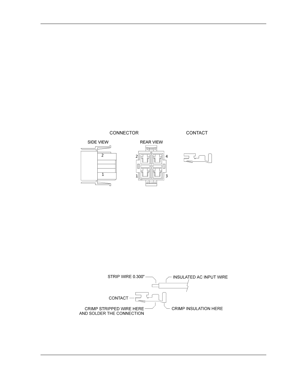
Figure 2-1 AC Connector and Contacts
W
IRE
P
REPARATION
1. Trim outer wire jacket 2". (Necessary for strain relief. See Section 2.5.4.)
2. Strip 0.300" at the end of the insulated AC input wire.
3. Crimp the stripped wire into the contact as indicated in Figure 2-2, then solder the
connection.
4. Crimp the contact around the wire insulation as indicated in Figure 2-2.
Figure 2-2 Wire Preparation