KBC Networks Mesh2HT User Manual
Page 19
Mesh2HT User Manual
Manual-MESH2HT-Rev1311
Copyright © KBC Networks 2012
Page 19 of 59
www.kbcnetworks.com
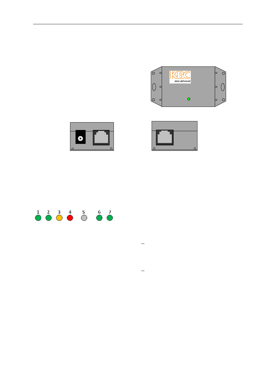
2.2.3 Power Injector Module (PIM)
Note:
The Power Injector Modules are not weatherproof units and must be protected
from moisture.
POE +
P
o
w
e
r
O
U
T
IN
Local Power
Remote Power
PIM Top View
PIM Side View (Power and Output)
PIM Side View (Input)
Note:
The Power injector is not required if connecting to an 802.3af PoE switch. If the
PIM is used, 24Vdc must be used.
2.2.4 RF Module LED Description
1. Signal Strength Indicator – 40 RSSI
If this LED is illuminated, the signal strength for R1 is > 40
2. Signal Strength Indicator – 30 RSSI
If this LED is illuminated, the signal strength for R1 is 30 ~ 39
3. Signal Strength Indicator – 20 RSSI
If this LED is illuminated, the signal strength for R1 is 20 ~ 29
4. Signal Strength Indicator – 10 RSSI
If this LED is illuminated, the signal strength for R1 is < 19
5. Not Used
6. Ethernet Link Activity
7. Power
Note:
The RSSI LEDs pertain to the signal strength of radio 1 (R1). If not illuminated,
R1 is not connected or is not being used.
1
2
2
3
1. Power – Power supply input
2. OUT – Connect to the Mesh2HT unit
3. IN – Connect to the Ethernet device