KBC Networks WESIIKT V221 17dBi to 17dBi Kit User Manual
Quick start guide
Quick Start Guide
WESII-KT
Host/Client Pt-to-Pt Wireless Ethernet Kit
Introduction
This document provides instruction for basic set
up and installation of the WESII-KT. More
detailed information can be found on the KBC
Networks website (see Downloads section).
Features of this QSG
Contents of the WESII-KT box
Necessary equipment to proceed
Web browser configuration steps
o
KBC default settings are usually
sufficient for operation
Default configurations restoration
process and details
LED indication
Support contact, FCC & Warranty Info
System Contents
Qty Description
1 WESII-AA-CA APHost RF module with integrated
directional antenna
1 WESII-AC-CA Client RF module with integrated
directional antenna
2 24VDC power supplies w/ integrated POE injector
2 Wall / pole-mount bracket and assembly kit (each
includes):
1 - Pole clamp bracket
1 - Bracket body (L/R swivel piece)
2 - Connecting pieces
(up/down alignment clamps)
1 - 50mm, 1.98” long 1/4” hex bolt
2 - ¼” hex nuts
1 - 27mm, 1.06” long ¼” hex bolt
2 - Flat washers 15mm, 0.59”
2 - Locking washers 10mm, 0.39” long
1 - U bolt
2 - ¼” lock washers
Downloads
Installation manual – includes other features &
functions:
(Click on Manuals&QSG, then Wireless, then Manuals
again)
Specification Sheets:
Equipment Required for Physical
Deployment
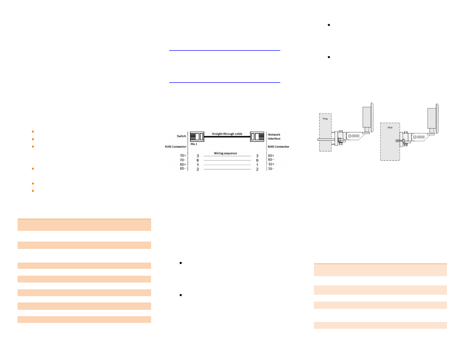
Two straight through Ethernet cables are
required for connection from the WESII APHost
or Client to the supplied PSU/PIM unit.
Note:
The power supply / injector device
supplied must be used with the WESII series.
KBC recommends shielded outdoor rated
Ethernet cables when connecting near power
outlets & when exposed to the elements.
Physical Deployment
This equipment must be installed and operated
in accordance with instructions found in the KBC
Networks’ manual. Damage due to misuse is not
covered by warranty. Here are some important
bullet points:
You will need to first feed the Ethernet
cable through the black strain relief (ie
weather coupler protection piece) prior
to crimping on the RJ45 connector.
Hand-tighten the Ethernet cable
connection protecting piece, do not
tighten further. Damage due to over-
tightening the black weather coupler into
its RJ45 housing is not covered under
warranty.
Do not mount the antennas horizontally
or upside down. The black external LAN
port is to be pointing downward with no
ability for water to get into the housing.
Once the cable is inserted into the
external LAN port RJ45, a small flat head
screwdriver, or similar tool, is needed to
release the tab of the RJ45 connector on
your cable. If you pull the cable without
releasing the tab, it will cause damage
to the port.
Default Configurations
The WESII-KT has been pre-set as a pair. The
WESII-AA-CA APHost is locked to its Client and
vice-versa. Refer to the serial number label on
each device which will indicate the serial number
of its mate radio. These two units have also
been physically strapped together because they
were factory set for another. A restore to
defaults to one or both devices will erase their
factory paired configuration resulting in the need
to field/bench re-configure. A restore to factory
defaults will return the units to the following:
Parameter
Setting
LAN IP Address
192.168.1.200 (AP-Host)
192.168.1.201 (Client)
GUI User ID
admin
GUI Password
password
SSID
KBC-WESII
Pre-shared Key
11111111
Frequency selection
(Host only)
Auto
Bandwidth
20/40 MHz
MAC-Filter
00:00:00:00:00:00