Devicenet remote i/o communication module rtu-dnet, 4 how to configure rtu-dnet, 3 connecting to devicenet connection port – Delta Electronics RTU-DNET User Manual
Page 10: 1 terms, Dvp-plc application manual 8
DeviceNet Remote I/O Communication Module RTU-DNET
DVP-PLC Application Manual
8
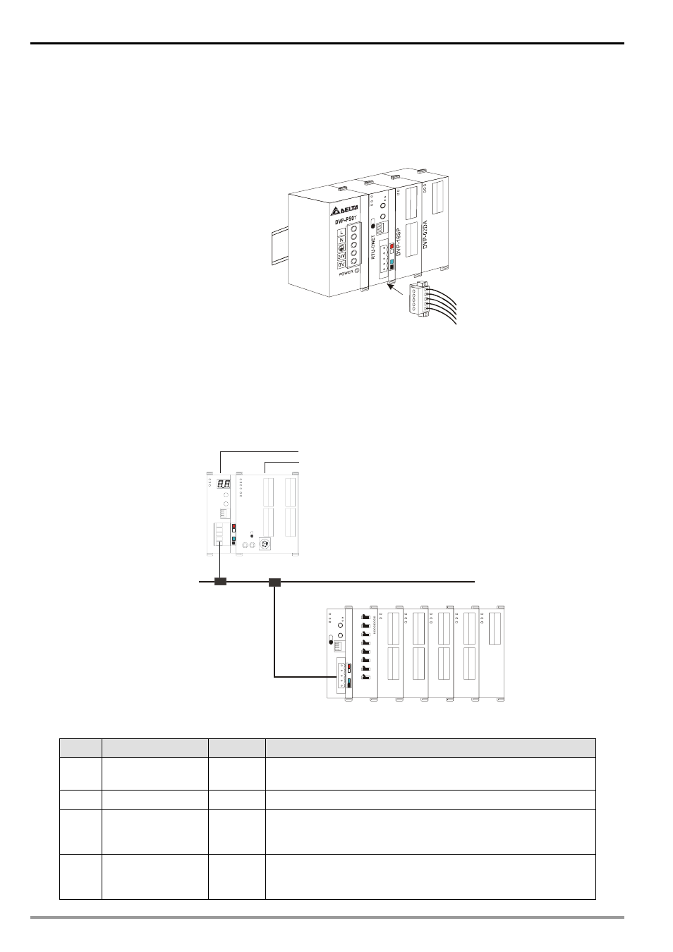
3.3 Connecting to DeviceNet Connection Port
z The colors on the PINs on the DeviceNet connection port match the colors of the connection cables. Make
sure you connect the cable to the right PIN.
z We recommend you also apply Delta’s power module in the connection.
4
How to Configure RTU-DNET
In this section we will introduce how RTU-DNET as a DeviceNet slave realizes the data exchange between
DeviceNet master and DVP Slim DI/DO extension unit.
z DeviceNet master sends the data to Slim DI/DO.
z RTU-DENT sends the input data from Slim DI/DO to DeviceNet master.
DeviceNet
DVP28SV
DVPDNET-SL
DVPDNET
DVP28SV
RU N
STOP
Master
R
T
U
-D
N
E
T
D
V
P
-0
2
D
A
D
V
P
-0
8
S
T
D
V
P
-1
6
S
P
D
V
P
-0
4
A
D
D
V
P
-0
4
T
C
D
V
P
-0
4
P
T
4.1 Terms
No.
Item
Unit
Explanation
1
Control word
Word
For setting up the mode of RTU-DNET, e.g. “H8000” for STOP
mode and “H8001” for RUN mode. See 4.3 for more details.
2
Status word
Word
Displaying the status of RTU-DNET. See 4.3 for more details.
3
Number of digital
input points
Bit
The digital input points shall be 8’s multiple. The number will be
regarded as 8 when it is less than 8 and as 16 when it is bigger
than 8 but less than 16.
4
Number of digital
output points
Bit
The digital output points shall be 8’s multiple. The number will be
regarded as 8 when it is less than 8 and as 16 when it is bigger
than 8 but less than 16.