Configuration push-button switches –15, Note 1) – Altera Cyclone IV GX Transceiver Starter Board User Manual
Page 23
Chapter 2: Board Components
2–15
Configuration, Status, and Setup Elements
© March 2010 Altera Corporation
Cyclone IV GX Transceiver Starter Board Reference Manual
lists the configuration settings DIP switch component reference and
manufacturing information.
Configuration Push-Button Switches
The PGM configure push-button switch, PGM_CONFIG (S1), is an input to the MAX
II
CPLD EPM2210 System Controller. The push-button switch forces a reconfiguration
of the FPGA from flash memory. The location in the flash memory is based on the
PGM_LED[1:0]
setting when the button is released. Valid settings include PGM_LED0
or PGM_LED1.
The PGM select push-button switch, PGM_SEL (S2), toggles the program LEDs (D3,
D4) sequence. Refer to
for the PGM_LED[1:0] sequence
definitions.
The MAX II reset push-button switch, MAX_RESETn (S3), resets the MAX II CPLD
EPM2210 System Controller.
lists the configuration push-button switches component reference and
manufacturing information.
JTAG – JTAG-based configuration
X
—
Notes to
:
(1) ON indicates a setting of ’0’ while OFF indicates a setting of ’1’.
(2) X indicates does not care. The JTAG-based configuration takes precedence over other configuration schemes and therefore, the FPGA_MSEL
pin settings are ignored.
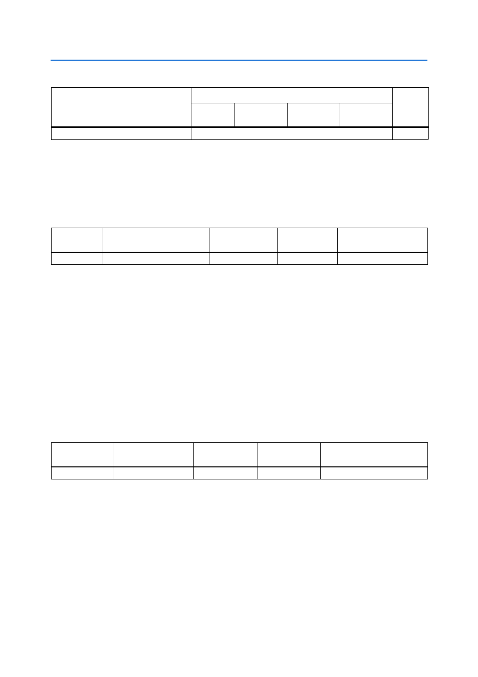
Table 2–13. Configuration Settings DIP Switch Controls (Part 2 of 2)
(Note 1)
Configuration Scheme
Setting
POR
Delay
EPCS_nCS
(S7.4)
FPGA_MSEL2
(S7.3)
FPGA_MSEL1
(S7.2)
FPGA_MSEL0
(S7.1)
Table 2–14. Configuration Settings DIP Switch Component Reference and Manufacturing Information
Board
Reference
Description
Manufacturer
Manufacturer
Part Number
Manufacturer Website
S8
Four-position slide DIP switch
C & K Components
TDA04H0SB1
Table 2–15. Configuration Push-button Switches Component Reference and Manufacturing Information
Board Reference
Description
Manufacturer
Manufacturer
Part Number
Manufacturer Website
S1-S3
Push-button switches
Panasonic
EVQPAC07K