Altera Cyclone IV GX Transceiver Starter Board User Manual
Page 18
2–10
Chapter 2: Board Components
Configuration, Status, and Setup Elements
Cyclone IV GX Transceiver Starter Board Reference Manual
© March 2010 Altera
Corporation
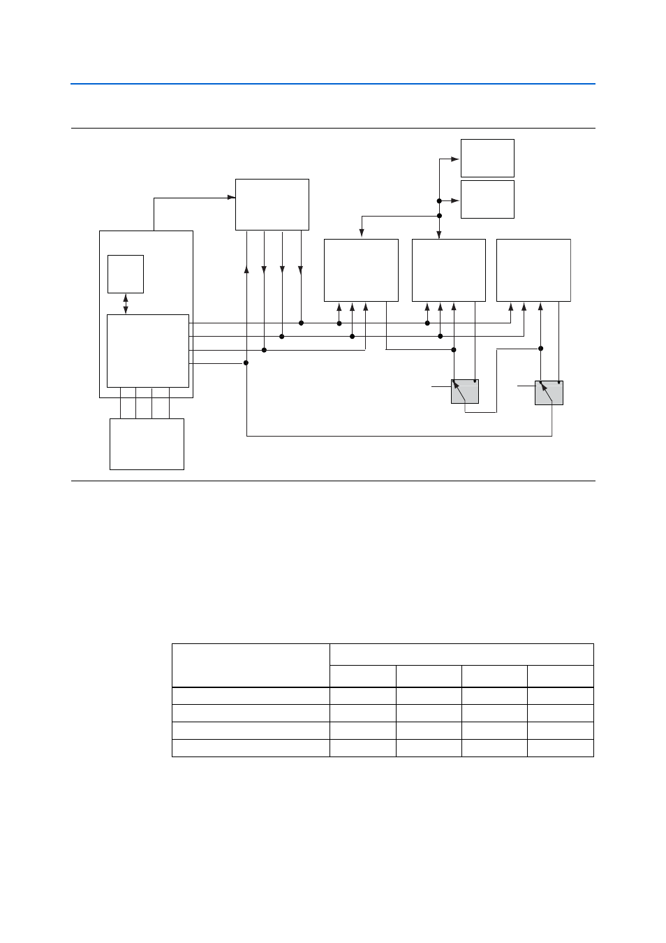
The Cyclone IV GX FPGA is configured via JTAG using the MAX II configuration
controller design (embedded blaster) as the primary configuration mode. The board
includes a MAX II CPLD EPM2210 System Controller which interfaces directly to the
Cyclone IV GX FPGA for configuration, LCD control, power monitor control, and
other purposes. The MAX II CPLD EPM2210 System Controller contains the required
state machine and control logic to determine the configuration source for the Cyclone
IV GX FPGA.
lists the Cyclone IV GX configuration modes.
Figure 2–4. JTAG Chain
GPIO
TCK
EP4CGX15BF14
FPGA
MAX II CPLD
EPM2210
System Controller
GPIO
TMS
GPIO
TDO
GPIO
TDI
USB_DISABLE
TCK TMS TDI TDO
JTAG
2 x 5 Header
Flash
128 Mb
USB
PHY
PCI Express
(Edge Gold Finger)
TCK TMS TDI TDO
TCK
TMS
TDI TDO
MAX II
EPM240M100
TCK
TMS
TDI TDO
SSRAM
18 Mb
JTAG
2 x 5 Header
TCK
TMS
TDI
TDO
EPM2210_JTAG_EN
PCIE_JTAG_EN
0
1
0
1
Embedded USB-Blaster
TCK TMS TDI TDO
Table 2–7. Cyclone IV GX Configuration Modes
Configuration Mode
Device
Flash
MAX II
EPCS
JTAG
Passive Serial (PS)
v
v
Active Serial (AS)
v
Flash Source
Numonyx
JTAG
v
v