After – Altera Cyclone IV GX Transceiver Starter Board User Manual
Page 22
2–14
Chapter 2: Board Components
Configuration, Status, and Setup Elements
Cyclone IV GX Transceiver Starter Board Reference Manual
© March 2010 Altera
Corporation
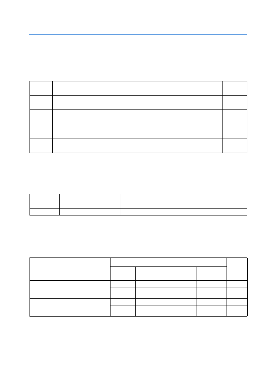
Board Settings DIP Switch
The board settings DIP switch (S8) controls various features specific to the board and
the MAX
II CPLD EPM2210 System Controller logic design.
shows the
switch controls and descriptions.
lists the board settings DIP switch component reference and
manufacturing information.
Configuration Settings DIP Switch
The configuration settings DIP switch (S7) controls the configuration scheme
selection. A configuration scheme with different configuration voltage standards is
selected by driving the MSEL pins either high or low, as shown in
Table 2–11. Board Settings DIP Switch Controls
Board
Reference Schematic Signal Name
Description
Default
S8.1
CLK_SEL
ON : On-board 125-MHz LVDS oscillator clock select
OFF : SMA input clock select
ON
S8.2
USER_PGM
ON: Load user hardware page 1 from flash memory upon power-up
OFF: Load factory design from flash memory upon power-up
OFF
S8.3
EPM2210_JTAG_EN
ON : Bypass Max II CPLD EPM2210 System Controller
OFF : Max II CPLD EPM2210 System Controller in-chain
OFF
S8.4
PCIE_JTAG_EN
ON : Bypass PCI Express
OFF : PCI Express in-chain
ON
Note to
:
(1) ON indicates a setting of ’0’ while OFF indicates a setting of ’1’.
Table 2–12. Board Settings DIP Switch Component Reference and Manufacturing Information
Board
Reference
Description
Manufacturer
Manufacturer
Part Number
Manufacturer Website
S8
Four-position slide DIP switch
C & K Components
TDA04H0SB1
Table 2–13. Configuration Settings DIP Switch Controls (Part 1 of 2)
Configuration Scheme
Setting
POR
Delay
EPCS_nCS
(S7.4)
FPGA_MSEL2
(S7.3)
FPGA_MSEL1
(S7.2)
FPGA_MSEL0
(S7.1)
Active Serial – Enables active serial
configuration with fast or standard
power-on-reset delay.
1
0
1
1
Fast
1
0
1
0
Standard
Passive Serial – Enables passive serial
configuration with fast or standard
power-on-reset delay.
0
1
0
0
Fast
0
0
0
0
Standard