Status elements, Setup elements, Status elements –13 setup elements –13 – Altera Cyclone IV GX Transceiver Starter Board User Manual
Page 21
Chapter 2: Board Components
2–13
Configuration, Status, and Setup Elements
© March 2010 Altera Corporation
Cyclone IV GX Transceiver Starter Board Reference Manual
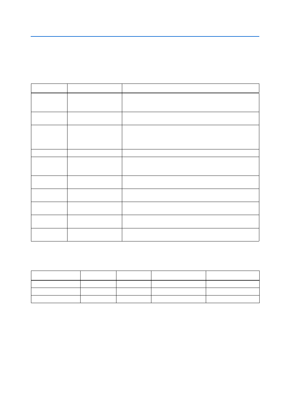
Status Elements
The starter board includes status LEDs. This section describes the status elements.
lists the LED board references, names, and functional descriptions.
lists the board-specific LEDs component references and manufacturing
information.
Setup Elements
The starter board includes several different kinds of setup elements. This section
describes the following setup elements:
■
Board settings DIP switch
■
Configuration settings DIP switch
■
Configuration push-button switches
Table 2–9. Board-Specific LEDs
Board Reference
LED Name
Description
D1
MAX_ERROR
Red LED. Illuminates when the MAX II CPLD EPM2210 System Controller
fails to configure the FPGA. Driven by the MAX II CPLD EPM2210 System
Controller.
D2
CONF_DONE_LED
Green LED. Illuminates when the FPGA is successfully configured. Driven
by the MAX II CPLD EPM2210 System Controller.
D3, D4
PROGRAM
(PGM_LED1,PGM_LED0)
Green LEDs. Illuminates to show the LED sequence that determines
which flash memory image loads to the FPGA when PGM select
push-button switch is pressed. Driven by the MAX II CPLD EPM2210
System Controller.
D12
Power
Blue LED. Illuminates when 9-V – 16-V power is active.
D13
USB_LED
Green LED. Illuminates when the embedded USB-Blaster is in use to
program the FPGA. Driven by the MAX II CPLD EPM2210 System
Controller and MAX IIZ.
D14
ENET_LEDR_TX
Green LED. Illuminates to indicate Ethernet PHY transmit activity. Driven
by the Marvell 88E1111 PHY.
D15
ENET_LEDR_RX
Green LED. Illuminates to indicate Ethernet PHY receive activity. Driven
by the Marvell 88E1111 PHY.
D16
ENET_LEDR_LINK1000
Green LED. Illuminates to indicate Ethernet linked at 1000 Mbps
connection speed. Driven by the Marvell 88E1111 PHY.
D17
ENET_LEDR_LINK100
Green LED. Illuminates to indicate Ethernet linked at 100 Mbps
connection speed. Driven by the Marvell 88E1111 PHY.
D18
ENET_LEDR_LINK10
Green LED. Illuminates to indicate Ethernet linked at 10 Mbps connection
speed. Driven by the Marvell 88E1111 PHY.
Table 2–10. Board-Specific LEDs Component References and Manufacturing Information
Board Reference
Description
Manufacturer
Manufacturer Part Number
Manufacturer Website
D1
Red LED
Lumex, Inc.
SML-LXT0805IW-TR
D2-D4, D13-D18
Green LEDs
Lumex, Inc.
SML-LX1206GC-TR
D12
Blue LED
Lumex, Inc.
SML-LX1206USBC-TR