Altera Cyclone II PowerPlay Early Power Estimator User Manual
Page 44
3–28
Altera
Corporation
PowerPlay Early Power Estimator User Guide For Cyclone II FPGAs
May 2006
Power Analysis
the case, thermal interface material and heat sink is referred to as the
junction-to-ambient thermal resistance (
θ
JA
).
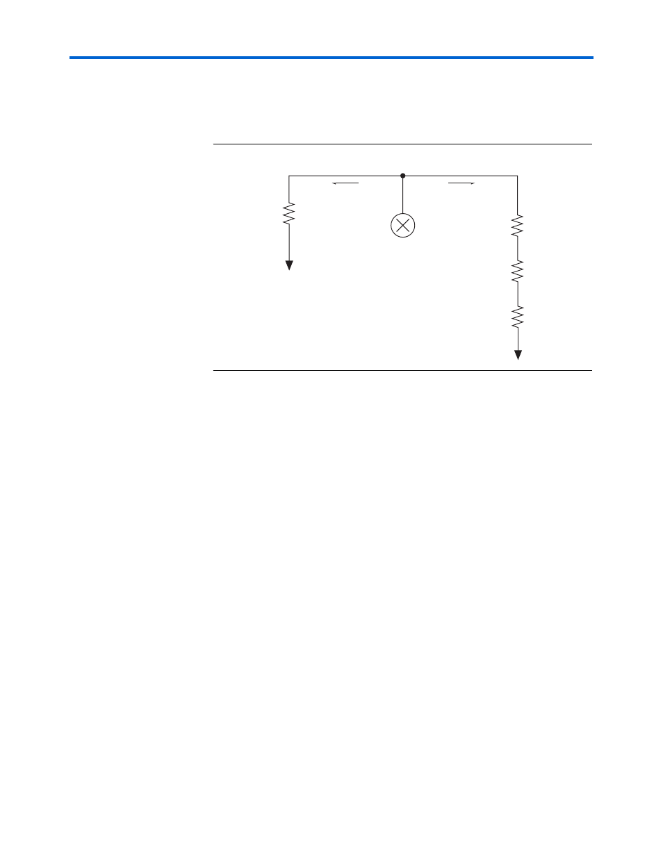
Figure 3–25
shows the
thermal model for the PowerPlay Early Power Estimator spreadsheet.
Figure 3–25. Thermal Model for EPE with a Heat Sink
If you want the PowerPlay Early Power Estimator spreadsheet thermal
model to take the junction-to-board thermal resistance (
θ
JB
) into
consideration, set the Board Thermal Model to either “Typical” or
“Custom.” A Typical board thermal model sets
θ
JB
to a value based on the
package and device selected. If you choose a Custom board thermal
model, you must specify a value for
θ
JB
. If you do not want the PowerPlay
Early Power Estimator spreadsheet thermal model to take the
θ
JB
resistance into consideration, set the Board Thermal Model to “None
(conservative).” In this case, the path through the board is not considered
and for power dissipation and a more conservative thermal power
estimate is obtained.
The junction-to-ambient thermal resistance (
θ
JA
) is determined by the
addition of the junction-to-case thermal resistance (
θ
JC
), the case-to-heat
sink thermal resistance (
θ
CS
) and the heat sink-to ambient thermal
resistance (
θ
SA
).
θ
JA
=
θ
JC
+
θ
CS
+
θ
SA
Based on the device, package, airflow, and the heat sink solution selected
in the main input parameters, the PowerPlay Early Power Estimator
spreadsheet determines the junction-to-ambient thermal resistance (
θ
JA
).
θ
JC
θ
CS
θ
SA
θ
JB
T
J
T
B
T
J
T
C
T
S
T
A
Power (P)
Power (P)
Heat Source