Using a heat sink – Altera Cyclone II PowerPlay Early Power Estimator User Manual
Page 43
Altera Corporation
3–27
May 2006
PowerPlay Early Power Estimator User Guide For Cyclone II FPGAs
Using the Cyclone II PowerPlay Early Power Estimator
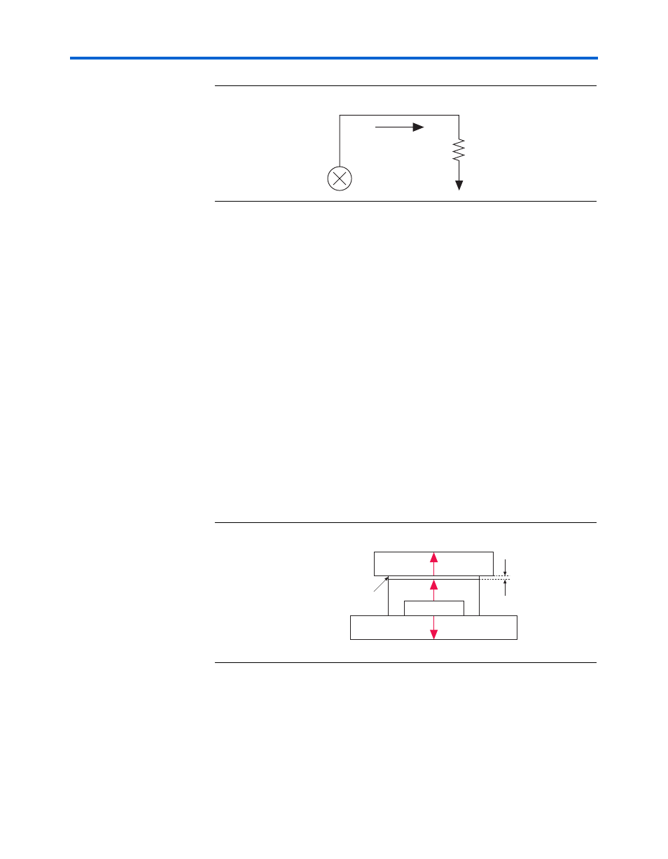
Figure 3–23. Thermal Model in EPE without a Heat Sink
The ambient temperature does not change, but the junction temperature
changes depending on the thermal properties. Since a change in junction
temperature affects the thermal device properties used to calculate
junction temperature, calculating junction temperature is an iterative
process.
The total power is calculated based on the device properties which
provide
θ
JA
and the ambient, board and junction temperatures using the
following equation:
P = (T
J
- T
A
) /
θ
JA
Using a Heat Sink
When a heat sink is used the major paths of power dissipation are from
the device through the case, thermal interface material, and heat sink.
There is also a path of power dissipation through the board. The path
through the board has much less impact than the path to air.
Figure 3–24
shows the thermal representation with a heat sink.
Figure 3–24. Thermal Representation with Heat Sink
In the model used in the early power estimator, power can be dissipated
through the board or through the case and heat sink. The thermal
resistance of the path through the board is referred to as the junction-to-
board thermal resistance (
θ
JB
). The thermal resistance of the path through
Power (P)
Heat
Source
T
J
T
A
θ
JA
Heat Sink
Case
Device
Board
Thermal Interface Material
θ
JB
θ
JC
θ
SA
Thermal Representation with Heat Sink
θ
CS