Altera Cyclone II PowerPlay Early Power Estimator User Manual
Page 38
3–22
Altera
Corporation
PowerPlay Early Power Estimator User Guide For Cyclone II FPGAs
May 2006
PowerPlay Early Power Estimator Spreadsheet Inputs
Each row in the Clocks section represents a clock network or a separate
clock domain. You must enter the clock frequency (f
MAX
) in MHz and the
total fanout for each clock network used.
Table 3–8
describes the
parameters in the Clock section of the PowerPlay Early Power Estimator
spreadsheet.
Figure 3–19
shows the Cyclone II PowerPlay Early Power Estimator
spreadsheet and the estimated power consumed by clocks for this design.
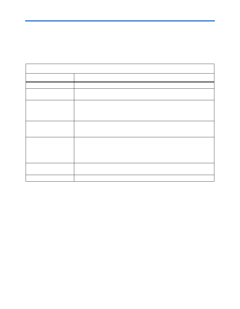
Table 3–8. Clock Section Information
Column Heading
Description
Domain
Enter a name for the clock network in this column. This is an optional value.
Clock frequency (MHz)
Enter the clock frequency for the clock network. This value is limited by the
maximum frequency specification.
Total Fanout
Enter the number of registers, multiplier blocks, and memory blocks driven by the
clock network. The number of resources driven by every global clock and regional
clock signal is reported in the Fan-out column of the Quartus II Compilation Report
under Fitter > Resource Section > Global & Other Fast Signals > Fan-out.
Global Enable %
Enter the average % of time that the entire clock tree is enabled. Each global clock
buffer has an enable signal that can be used to dynamically shut down the entire
clock tree.
Local Enable %
Enter the average % of time that clock enable is high for destination flip flops. Local
clock enables for flip flops in the LEs are promoted to logic array block (LAB)-wide
signals. When a given flip flop is disabled, the LAB-wide clock is also disabled,
cutting clock power in addition to power for down-stream logic. This sheet models
only the impact on clock tree power.
Total Power
This shows the estimated power in W, based on the f
MAX
and total fan-out you
entered. This value is calculated automatically.
User Comments
Enter any comments. This is an optional entry.