Using remote system upgrade – Altera Parallel Flash Loader IP User Manual
Page 20
Using Remote System Upgrade
When you instantiate the PFL IP core in the Altera CPLD for FPP or PS configuration, you can use the
features in the PFL IP core to perform remote system upgrade.
You can download a new configuration image from a remote location, store it in the flash memory device,
and direct the PFL IP core to trigger an FPGA reconfiguration to load the new configuration image. You
must store each configuration image as a new page in the flash memory device. The PFL IP core supports
a maximum of eight pages.
When using remote system upgrade, the configuration images are classified as a factory image or as
application images. A factory image is a user-defined fall-back or safe configuration that performs system
recovery when unintended errors occur during or after application image configuration. The factory
image is written to the flash memory device only once by the system manufacturer and you must not
modify or overwrite the factory image. Application images implement user-defined functionality in the
target FPGA and you can remotely update in the system.
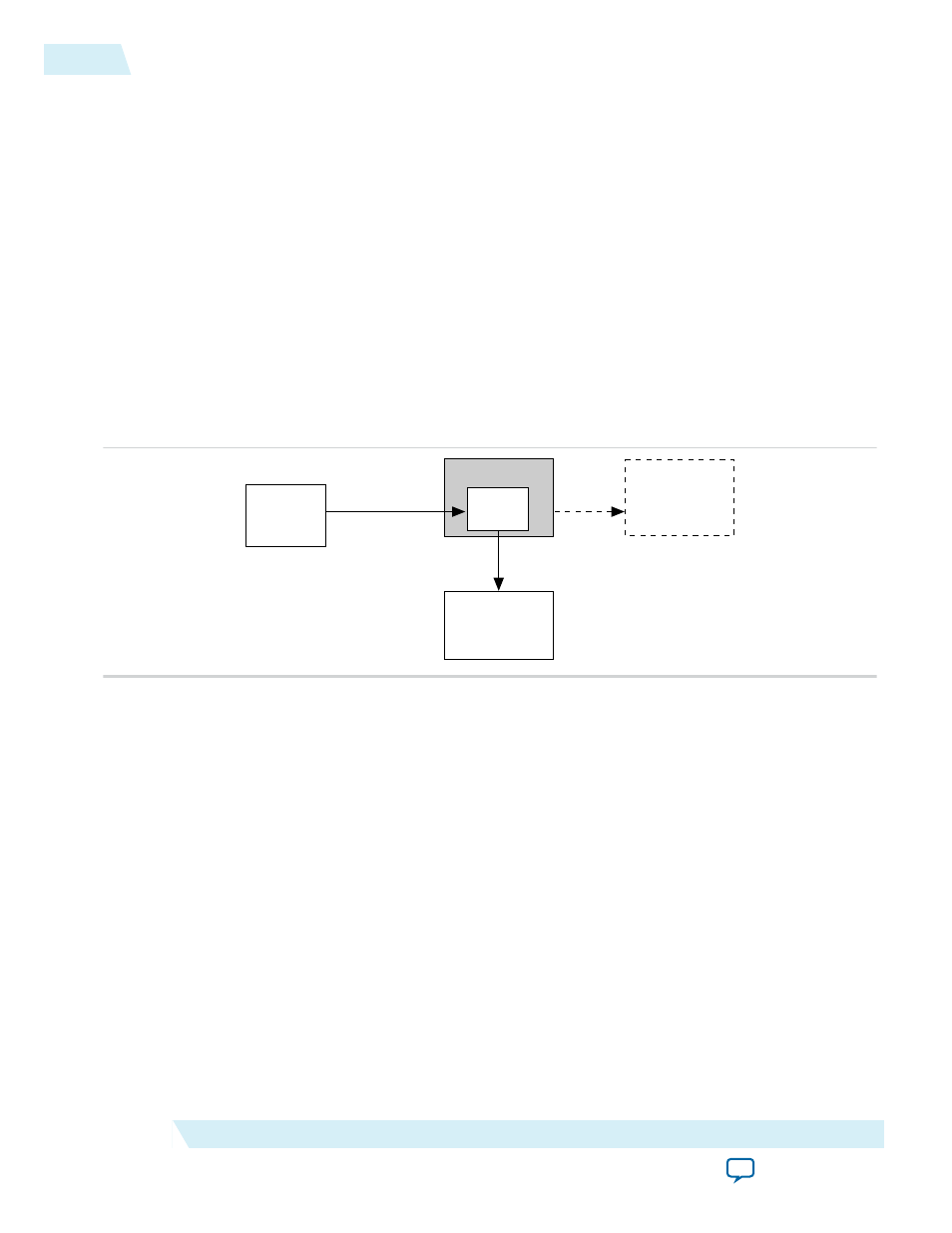
Figure 17: Remote System Upgrade Implementation with the PFL IP Core in FPP and PS Configuration
Scheme
Altera CPLD
CFI Flash
Memory
Altera
FPGA
Configuration Data
Common
Flash
Interface
PFL
Quartus II
Software
via JTAG
Altera FPGA Not Used
for Flash Programming
Remote System Upgrade State Machine in the PFL IP Core
After FPGA powers up, you have the flexibility to determine whether a factory image or any application
image is to be loaded by setting the
fpga_pgm[2..0]
input pin to the page in which the intended
configuration image is stored.
If an error occurs while loading the configuration image, the PFL IP core triggers a reconfiguration to
automatically load the factory image. After the FPGA successfully loads the configuration image, the
FPGA enters user mode. After the FPGA enters user mode, you can initiate a reconfiguration to a new
page by following these steps:
1. Set the
fpga_pgm[2.0]
input pin.
2. Release the
pfl_nreset
to high if the
pfl_nreset
is asserted to low.
3. After four or five clock cycles, pulse the
pfl_nreconfigure
input pin to low.
4. Ensure that all transition is synchronized to
pfl_clk
.
20
Using Remote System Upgrade
UG-01082
2015.01.23
Altera Corporation
Parallel Flash Loader IP Core User Guide