Altera Parallel Flash Loader IP User Manual
Page 17
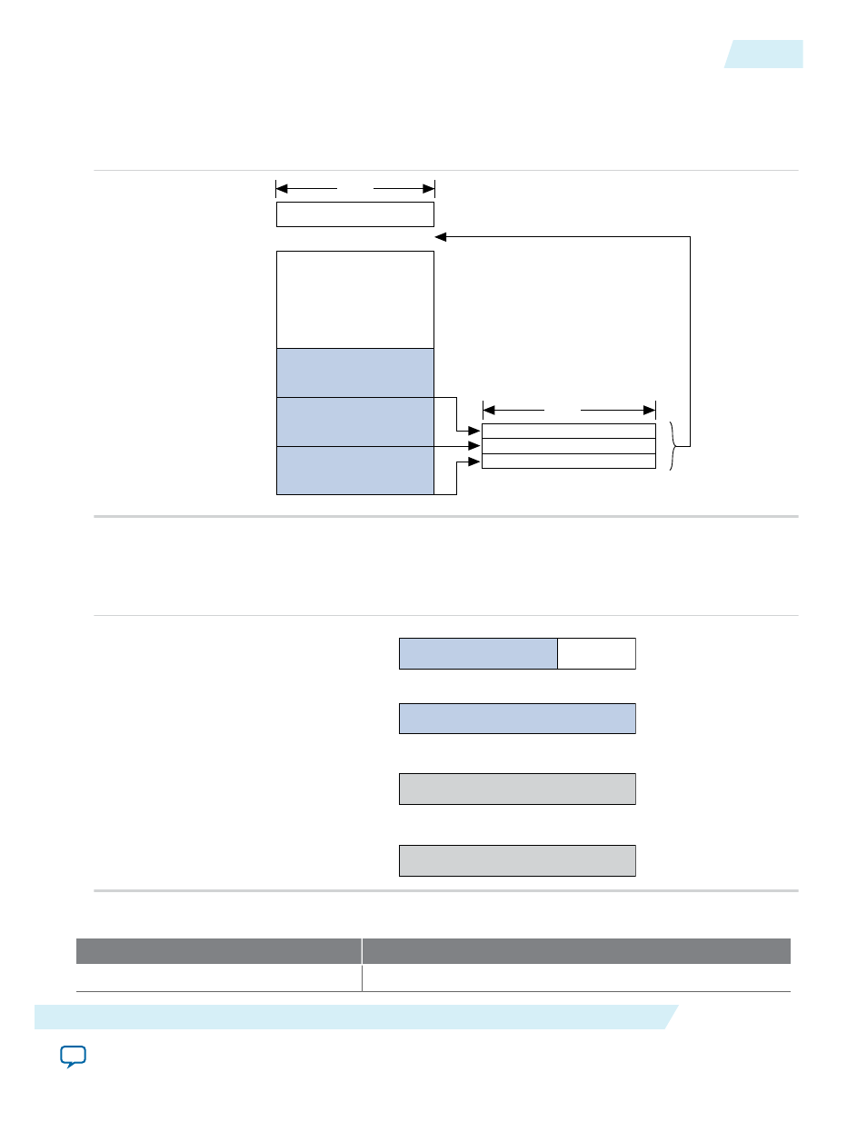
Figure 13: Implementing Page Mode and Option Bits in the CFI Flash Memory Device
• The end address depends on the density of the flash memory device. For the address range for devices
with different densities, refer Byte Address Range table.
• You must specify the byte address for the option bits sector.
Option Bits
Configuration Data (Page 2)
Configuration Data (Page 1)
Configuration Data (Page 0)
Page 2 Address + Page-Valid
Page 1 Address + Page-Valid
Page 0 Address + Page-Valid
End Address
0x000000
8 Bits
32 Bits
Figure 14: Page Start Address, End Address, and Page-Valid Bit Stored as Option Bits
Bits 0 to 12 for the page start address are set to zero and are not stored as option bits. The Page-Valid bits
indicate whether each page is successfully programmed. The PFL IP core programs the Page-Valid bits
after successfully programming the pages.
Page Start Address [19:13]
Page-Valid
Bit 7...Bit 1
Bit 0
Page Start Address [27:20]
Bit 7...Bit 0
0x002000
0x002001
Page End Address [19:13]
Bit 7...Bit 1
0x002002
Page End Address [27:20]
Bit 7...Bit 0
0x002003
(For flash byte addressing mode)
Table 5: Byte Address Range for CFI Flash Memory Devices with Different Densities
CFI Device (Megabit)
Address Range
8
0x0000000
–
0x00FFFFF
UG-01082
2015.01.23
Storing Option Bits
17
Parallel Flash Loader IP Core User Guide
Altera Corporation