7 reaction and processing times, 1 reaction times with fast shutdown, 2 input/output processing time – Pilz PSSu K F FCU User Manual
Page 17: Reaction and processing times, Reaction times with fast shutdown, Input/output processing time
Function description
Operating Manual PSSu K F FCU
1002391-EN-04
17
Reaction and processing times
Reaction times with fast shutdown
During fast shutdown, the overall reaction time is the period that elapses between a signal
changing at the input and a signal changing at the output. It depends on the configured in-
put filter time and various influences such as internal run times, temperature drifts, spread
of components, etc.
Maximum reaction time for shutdown with falling edge:
t
FS
-
overall reaction time max
= (
t
configured input filter time
+ 0,450 ms)
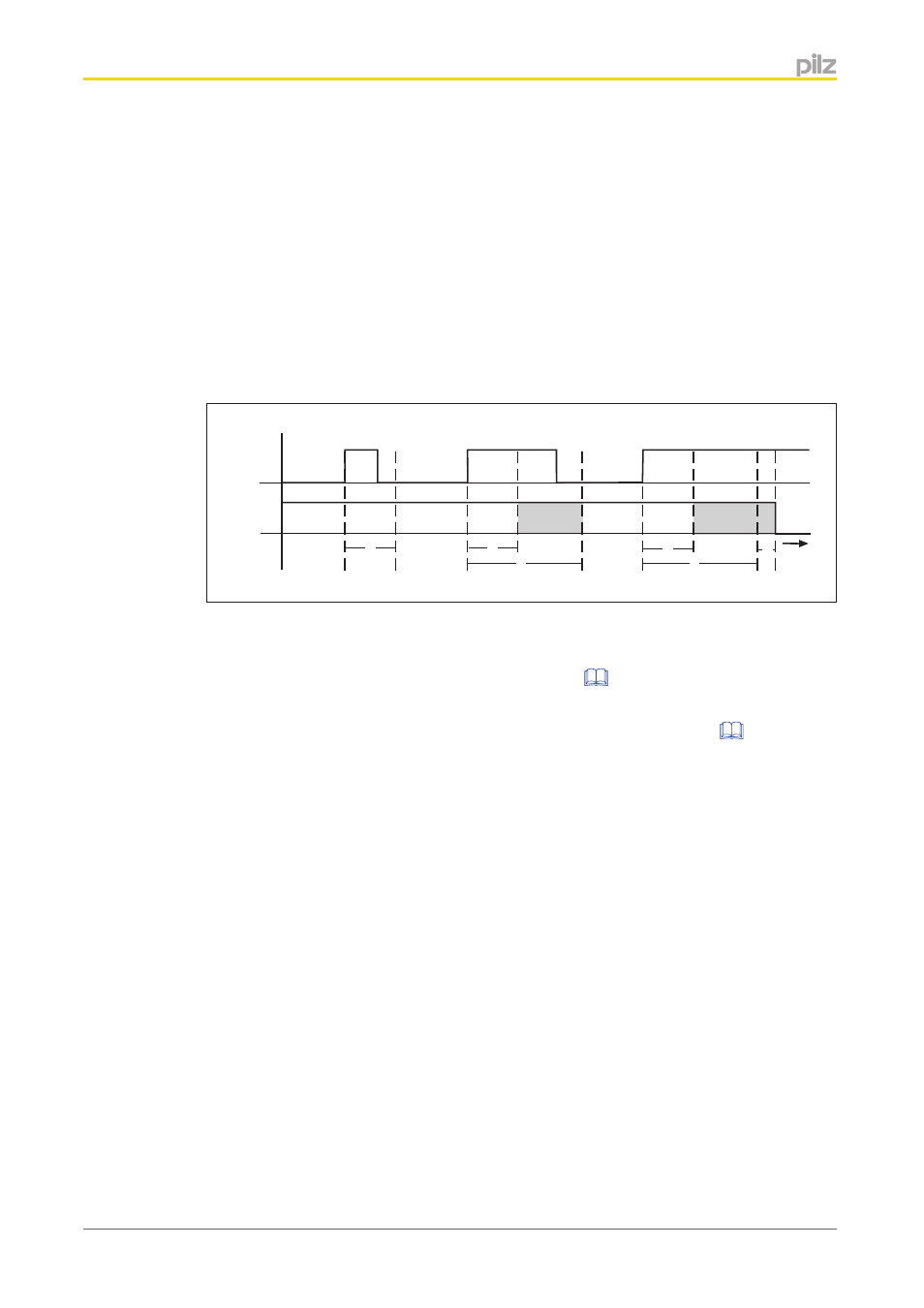
Timing diagram for fast shutdown with a configured input filter time:
Input
t
Output
t
2
t
1
t
1
t
1
t
2
t
3
}
Input: Signal at the input
}
Output Signal at the output
}
t
1
Safely filtered out signal time see
}
t
2
Configured input filter time
}
t
3
Max. processing time of semiconductor output see
Shaded area: Output state not defined
Input/output processing time
The processing time of the inputs and outputs applies for all inputs and outputs that are
used without fast shutdown. It is the time a module requires for processing signal changes.
It also takes into account the configured input filter time and various influences such as in-
ternal run times, temperature drifts, spread of components etc. To establish the reaction
times, the the module bus cycle time needs to be considered in addition to the processing
time. Information on the reaction times of the inputs and outputs can be found in the system
description PSSuniversal.
4.7
4.7.1
4.7.2