Pilz PNOZ pe1p User Manual
Page 5
- 5 -
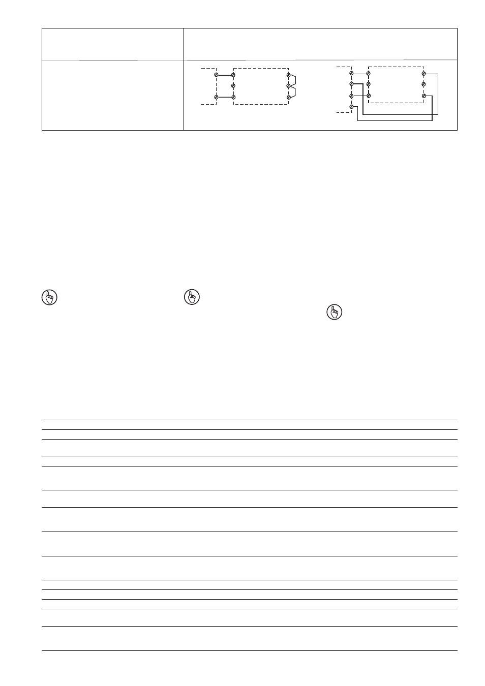
Querschlusserkennung abhängig von
übergeordneter Steuerung
Detection of shorts across contacts depends
on master controller
Détection des courts-circuits dépendant du
système de commande maître
➀
Digitale Ausgänge gegen Minus schaltend
➁
Digitale Ausgänge gegen Masse schaltend
Betrieb
Das Gerät ist betriebsbereit, wenn die LED
"POWER" leuchtet.
Statusanzeigen:
• "K1" und "K2" leuchtet: Das Ausgangssignal
auf dem PNOZpower-Bus zur Ansteuerung
der Erweiterungsmodule ist gesetzt.
• "K1" bzw. "K2" erlischt: Das Ausgangssignal
auf dem PNOZpower-Bus zur Ansteuerung
der Erweiterungsmodule ist nicht gesetzt.
Fehleranzeige:
• LED "FAULT" leuchtet:
Interner Fehler, Verdrahtungsfehler oder
Querschluss
Wichtig
Die elektronische Sicherung und die
LED „FAULT“ funktionieren nur, wenn
die Klemme S11 angeschlossen ist.
Nur dann erkennt das PNOZ pe1p
Querschlüsse. Ist die Klemme S11
nicht angschlossen, muss die überge-
ordnete Steuerung Querschlüsse
überwachen.
• LED "POWER" leuchtet nicht: Kurzschluss
oder Versorgungsspannung fehlt.
Operation
The unit is ready for operation when the
“POWER” LED is lit.
Status indicators:
• “K1” and “K2” are lit: The output signal on
the PNOZpower bus controlling the
expansion modules is set.
• “K1” or “K2” unlit: The output signal on the
PNOZpower bus controlling the expansion
modules is not set.
Error indicator:
• “FAULT” LED is lit:
Internal error, wiring error or short across
contacts
Notice
The electronic fuse and “FAULT” LED
only work when terminal S11 is
connected. Only then can the
PNOZ pe1p detect shorts across
contacts. If terminal S11 is not
connected, the master controller must
monitor for shorts across contacts.
• LED “POWER” does not light: short circuit
or power supply failure.
➀
Digital outputs, negative-switching
➁
Digital outputs, earth-switching
➀
Sorties digitales commutées par rapport au
moins
➁
Sorties digitales commutées par rapport à
la masse
S21
Y4
S11
K1
K2
Y3
O1
O2
➁
S21
Y4
S11
K1
K2
Y3
O1+
O1-
O2+
O2-
➀
Eingangskreis
Input circuit
Circuit d'entrée
Einkanalig, Ansteuerung durch Halbleiterausgänge
Dual-channel, driven via semiconductor outputs
Commande par 2 canaux, commande par sorties statiques
Fonctionnement
L'appareil est prêt à fonctionner, quand la
LED "POWER" est allumée .
Affichage état:
• "K1" et "K2" sont allumées : le signal de
sortie pour le pilotage du module
d'extension est envoyé sur le bus du
PNOZpower
• "K1" ou "K2" est éteinte : le signal de
sortie pour le pilotage du module
d'extension n'est pas envoyé sur le bus du
PNOZpower
Affichage erreur :
• LED "FAULT" est allumée :
défaut interne, erreur de câblage ou court-
circuit
Important
Le fusible électronique et la LED
„FAULT“ ne fonctionne que si la borne
S11 est raccordée. Le PNOZ pe1p
peut alors détecter les courts-circuits.
Si la borne S11 n'est pas raccordée, la
détection des courts-circuits doit être
réalisée par le système de commande
maître.
• LED "POWER" ne s'allume pas : court-
circuit ou tension d'alimentation non
présente.
Technische Daten
Versorgungsspannung
Spannungstoleranz
Leistungsaufnahme bei U
B
ohne Last
Restwelligkeit U
B
Spannung und Strom an
Eingangskreis
Rückführkreis
Überbrückung bei
Spannungseinbrüchen
Einschaltverzögerung (ohne
Einschaltverzögerung der
Erweiterungsmodule)
Rückfallverzögerung (ohne
Einschaltverzögerung der
Erweiterungsmodule)
Luft- und Kriechstrecken nach
EN 60947-1
Verschmutzungsgrad
Bemessungsisolationsspannung
Bemessungsstoßspannungsfestigkeit
Klimabeanspruchung
EMV
Schwingungen nach
Frequenz
Amplitude
Technical details
Supply voltage
Voltage tolerance
Power consumption at U
B
without load
Residual ripple U
B
Voltage and current at
Input circuit
feedback loop
Supply interruption before
de-energisation
Switch-on delay (excluding switch-on
delay of expansion modules)
Delay-on de-energisation (excluding
switch-on delay of expansion
modules)
Airgap creepage to
EN 60947-1
Pollution degree
Rated insulation voltage
Rated impulse withstand voltage
Climatic suitability
EMC
Vibration to
Frequency
Amplitude
Caractéristiques techniques
Tension d’alimentation
Plage de la tension d'alimentation
Consommation pour U
B
sans charge
Ondulation résiduelle U
B
Tension et courant sur
Circuit d’entrée
boucle de retour
Tenue aux micro-coupures
Temps de réarmement (sans le
temps de réarmement du module
d‘extension)
Temps de retombée (sans le temps
de retombée du module d‘extension)
Cheminement et claquage d’après
EN 60947-1
Niveau d’encrassement
Tension assignée d’isolement
Tension assignée de tenue aux chocs
Sollicitations climatiques
CEM
Oscillations selon
fréquence
amplitude
24 V DC
-15 % ...+10 %
2 W
DC: 160 %
24 V DC/50 mA
24 V DC/50 mA
max. 10 ms
max. 10 ms
max. 30 ms
2
60 V
0,8 kV
EN 60068-2-78
EN 60947-5-1,
EN 61000-6-2
EN 60068-2-6
10...55 Hz
0,35 mm