Pilz PNOZ pe1p User Manual
Page 2
- 2 -
• Verbindung zwischen dem PNOZ pe1p
und den Erweiterungsmodulen über den
PNOZpower-Bus durch Steckbrücke auf
der Geräterückseite
• Statusanzeige für Ausgangsrelais,
Versorgungsspannung und Störung
• Anschluss für Rückführkreis
Funktionsbeschreibung
Das Ansteuermodul dient zusammen mit den
Erweiterungsmodulen der Erweiterung eines
Sicherheitsstromkreises. Es wird von einer
übergeordneten Steuerung (z. B. sichere
Ausgänge einer PSS) angesteuert.
Nach Anlegen der Versorgungsspannung
von 24 V DC an die Klemmen A1 und A2
leuchtet die LED "POWER".
• Liegen 24 V DC an K1-Y3, dann geht das
Relais K1 in Wirkstellung. Die Statusan-
zeige "K1" leuchtet.
• Liegen 24 V DC an K2-Y4, dann geht das
Relais K2 in Wirkstellung. Die Statusan-
zeige "K2" leuchtet.
• Das Ausgangssignal auf dem
PNOZpower-Bus zur Ansteuerung der
Erweiterungsmodule wird gesetzt, wenn
K1 und K2 in Wirkstellung sind.
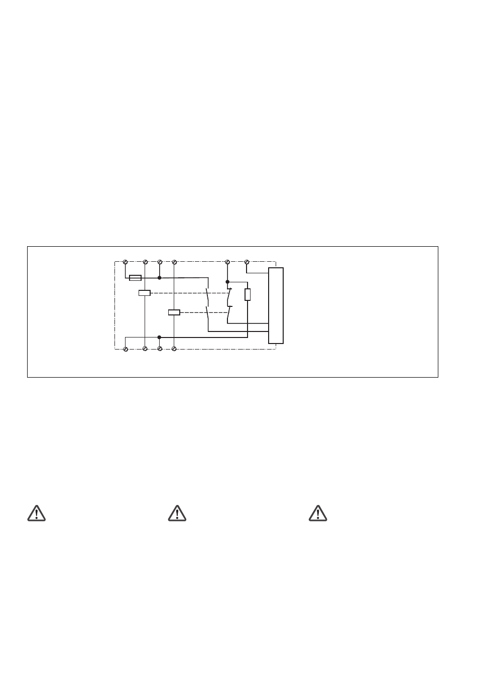
Innenschaltbild
Internal wiring diagram
Betriebsarten:
• Einkanaliger Betrieb: Einkanaliger
Betrieb: EN 60204-1 (VDE 0113-1) und
IEC 60204-1, keine Redundanz im
Eingangskreis, Erdschlüsse im Eingangs-
kreiswerden erkannt.
• Zweikanaliger Betrieb: Erdschlüsse im
Eingangskreis und Querschlüsse zwischen
den Eingangskreiskontakten werden
erkannt. Bei Verwendung von Halbleiter-
ausgängen ist das Erkennen von Quer-
schlüssen von der übergeordneten
Steuerung abhängig.
Sicherheitsschaltgerät montieren
Achtung! Montieren Sie das
Sicherheitsschaltgerät in einen
Schaltschrank mit einer Schutzart von
mindestens IP54.
• Befestigen Sie das Gerät mit Hilfe der zwei
Rastelemente auf der Rückseite auf einer
Normschiene.
• Das Sicherheitsschaltgerät muss in einen
Schaltschrank (min. IP 54) eingebaut
werden. Zur Befestigung auf einer
Tragschiene dienen zwei Rastelemente
auf der Rückseite des Geräts.
• Montieren Sie das Gerät auf eine waag-
rechte Tragschiene. Bei anderen Einbau-
lagen können die in den techn. Daten
angegebenen Werte für das Schalt-
vermögen nicht eingehalten werden.
K1
Y3
A1
Y4
K1
K2
PNOZpo
w
er-Bus
A2
K2
S11
S21
Y1
Y2
• Connection between the PNOZ pe1p and
expansion modules via the PNOZpower
bus, employing jumpers on the rear face of
the unit.
• Status indicator for output relay, supply
voltage and fault
• Connection for feedback loop
Function description
The control module, in conjunction with the
expansion modules, is used to expand a
safety circuit. It is driven from a master
controller (e.g. safe outputs on a PSS).
When the supply voltage of 24 VDC is
applied to terminals A1 and A2, the “PO-
WER” LED will light.
• If 24 VDC are present at K1-Y3, relay K1
will energise. The status LED “K1” will
light.
• If 24 VDC are present at K2-Y4, relay K2
will energise. The status LED “K2” will
light.
• The output signal on the PNOZpower bus
controlling the expansion module will be
set if K1 and K2 are energised.
Operating modes:
• Single-channel mode: Single channel
mode: EN 60204-1 (VDE 0113-1) and IEC
60204-1, no redundancy in the input circuit,
earth faults in the input circuit will be
detected.
• Dual-channel mode: Earth faults in the
input circuit and shorts between the input
circuit contacts will be detected. If
semiconductor outputs are used, the
detection of shorts across contacts will
depend on the master controller.
Installing the safety relay
Caution! The safety relay should be
installed in a control cabinet with a
protection type of at least IP54.
• Use the two notches on the back of the
unit to attach it to a DIN rail.
• The safety relay must be installed in a
control cabinet (min. IP54). There are two
notches on the back of the unit for DIN rail
attachment.
• Fit the unit to a horizontal DIN rail. In other
mounting positions, the values given in the
technical details for the switching capability
may not be achieved.
• Raccordement entre le PNOZ pe1p et les
modules d'extension par le bus du
PNOZpower à l'aide de connecteurs
enfichables sur l'arrière du relais
• Affichage de l'état du relais de sortie, de
l'alimentation et des défauts
• Raccordement pour boucle de retour
Description du fonctionnement
Le module de commande permet en liaison
avec un module d'extension, la coupure d'un
circuit de sécurité. Il est piloté par un élément
maître (par ex. sorties de sécurité d'un PSS)
.
Après application de la tension d'alimenta-
tion 24 V DC sur les bornes A1 et A2, la
LED "POWER" s'allume.
• Si le 24 V DC est présent aux bornes K1-
Y3, le relais K1 passe en position travail.
La LED "K1" s'allume.
• Si le 24 V DC est présent aux bornes K2-
Y4, le relais K2 passe en position travail.
La LED "K2" s'allume.
• Le signal de sortie est activé sur le bus du
PNOZpower dès que K1 et K2 sont en
position travail.
Modes de fonctionnement :
• Commande par 1 canal : EN 60204-1
(VDE 0113-1) et IEC 60204-1, pas de
redondance dans le circuit d'entrée, la
mise à la terre du circuit d'entrée est
détectée.
• Commande par 2 canaux: la mise à la
terre et les courts-circuits entre les canaux
sont détectés. En cas de pilotage par
sorties statiques, la détection des courts-
circuits dépend du dispositif de commande
maître.
Installer le bloc logique de sécurité
Attention! Installez le bloc logique de
sécurité dans une armoire d’indice de
protection au moins IP54.
• Montez l'appareil sur un rail DIN à l'aide du
système de fixation situé au dos du relais.
• Montez l'appareil sur un rail horizontal. En
cas de montage différent, les valeurs des
caractéristiques de commutation indiquées
dans les caractéristiques techniques ne
sont plus respectées.
• Le module de commande PNOZ pe1p
peut être inséré à n'importe quelle place
dans le système modulaire PNOZpower.
Schéma interne