Pilz PNOZ pe1p User Manual
Page 4
- 4 -
S21
Y4
S11
K1
K2
Y3
Beispiel (Betriebsart: zweikanalig):
- Leitungsquerschnitt: 1,5 mm
2
- Temperatur:
+25 °C
- Leitungskapazität:
150 nF
- Max. Gesamtleitungswiderstand R
lmax
:
14
Ω
- Leitungswiderstand R
l
/km:
28
Ω
/km
- Max. Leitungslänge I
max
:
14 W
28 W / km
» 0,5 km
I
max
=
Wichtig
Das Beispiel zur Berechnung der
maximalen Leitungslänge gilt nur in
den Fällen, bei denen das PNOZ pe1p
den Querschluss überwacht. Bei
Ansteuerung durch Halbleiteraus-
gänge ist die maximale Leitungslänge
von der übergeordneten Steuerung
abhängig.
Betriebsbereitschaft herstellen:
• Legen Sie die Versorgungspannung an:
Klemme A1 : + 24 V DC
Klemme A2 : 0 V
• Legen Sie die Betriebsart mit/ohne
Querschlusserkennung durch Verdrahten
der Eingangskreise fest.
• Überwachung des Rückführkreises:
- bei Ansteuerung durch Halbleiteraus-
gänge:
Klemme Y1: + 24 V DC
Klemme Y2: mit einem sicherem
Eingang der übergeordneten Steuerung
verbinden
- bei Ansteuerung durch Sicherheits-
kontakte:
Klemmen Y1 und Y2 mit dem Rückführ-
kreis des Sicherheitsschaltgeräts
verbinden.
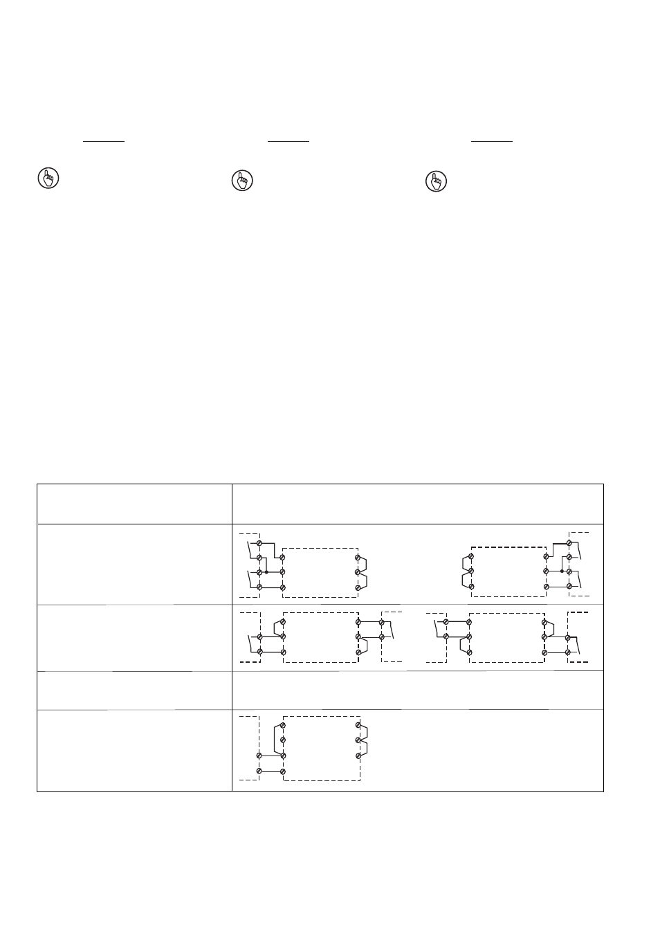
Eingangskreis
Input circuit
Circuit d'entrée
Zweikanalig, Ansteuerung durch Sicherheitskontakte
Dual-channel, driven via safety contacts
Commande par deux canaux, commande par contacts de sécurité
ohne Querschlusserkennung
without detection of shorts across contacts
sans détection des court-circuits
mit Querschlusserkennung
with detection of shorts across contacts
sans détection des court-circuits
S21
Y4
S11
K1
K2
Y3
S21
Y4
S11
K1
K2
Y3
S21
Y4
S11
K1
K2
Y3
ohne Querschlusserkennung
without detection of shorts across contacts
sans détection des court-circuits
Eingangskreis
Input circuit
Circuit d'entrée
Einkanalig, Ansteuerung durch Halbleiterausgänge
Single-channel, driven via semiconductor outputs
Commande par 1 canal, commande par sorties statiques
Example (operating mode: dual-channel):
- Cable cross section: 1.5 mm
2
- Temperature:
+25 °C
- Cable capacitance:
150 nF
- Max. overall cable resistance R
lmax
:
14
Ω
- Cable resistance R
l
/km:
28
Ω
/km
- Max. cable runs l
max
:
14 W
28 W / km
» 0,5 km
I
max
=
Notice
The example for calculating the
maximum cable runs is only valid
where the PNOZ pe1p is monitoring for
shorts across contacts. When driven
via semiconductor outputs, the
maximum cable runs will depend on
the master controller.
Preparing for operation:
• Supply voltage should be applied to:
Terminal A1 : +24 VDC
Terminal A2 : 0 V
• Establish the operating mode with/without
detection of shorts across contacts through
the wiring of the input circuits.
• Monitoring the feedback loop:
- when driven via semiconductor outputs:
Terminal Y1: +24 VDC
Terminal Y2 : connect to a safe input on
the master controller
- when driven via safety contacts:
Connect terminals Y1 and Y2 to the
feedback loop on the safety relay.
Exemple (mode de fonctionnement : deux
canaux ):
- Diamètre du câble :
1,5 mm
2
- Température :
+25 °C
- Capacité du câble :
150 nF
- Résistivité max. du câblage R
lmax
: 14
Ω
- Résistivité du câble R
l
/km:
28
Ω
/km
- Longueur maximale du câblage I
max
:
14 W
28 W / km
» 0,5 km
I
max
=
Important
L'exemple de calcul de la longueur
maximale du câblage n'est valable
qu'en cas de détection des courts-
circuits par le PNOZ pe1p . En cas de
commande par des sorties statiques, la
longueur maximale du câblage dépend
du système de commande maître.
Mettre en oeuvre le système :
• Appliquez la tension d'alimentation :
borne A1 : + 24 V DC
borne A2 : 0 V
• Choisissez le mode avec/sans détection
des courts-circuits par câblage du circuit
d'entrée
• Surveillance de la boucle de retour :
- en cas de commande par sorties
statiques :
borne Y1: + 24 V DC
borne Y2: à relier à une entrée de
sécurité du système de commande
maître
- en cas de commande par contacts de
sécurité :
bornes Y1 et Y2 à relier au circuit de
boucle de retour du relais de sécurité.
S21
Y4
S11
K1
K2
Y3
O+
GND
A2
➁