Pilz PNOZ pe1p User Manual
Page 3
- 3 -
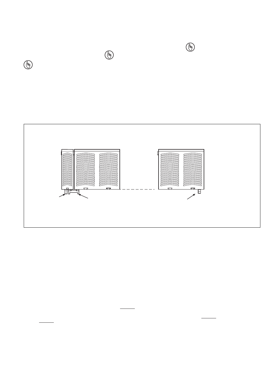
• Das Ansteuermodul PNOZ pe1p kann an
beliebiger Stelle des modularen Sicher-
heitssystems PNOZpower montiert
werden.
• Auf der Geräterückseite des PNOZ pe1p
befinden sich 2 Buchsen. Das An-
steuermodul PNOZ pe1p wird mit den
Erweiterungsmodulen über die mitgeliefer-
ten Steckbrücken verbunden.
Wichtig Auf das erste und letzte Gerät
muss ein Abschlussstecker gesteckt
werden (siehe Fig. "Montage des
PNOZ pe1p")!
• Nur Abschlussstecker für das modulare
Sicherheitssystem PNOZpower verwenden
(Aufdruck: PNOZ p 95579).
• Maximalbestückung eines PNOZpower-
Systems:
- 1 Ansteuermodul PNOZ pe1p
- 4 Erweiterungsmodule
- 1 Netzgerät
Montage des PNOZ pe1p
Installation PNOZ pe1p
Erweiterungsmodul 1
Expander module 1
Module d'expansion 1
Erweiterungsmodul 4
Expander module 4
Module d'expansion 4
95579
Abschlussstecker
Terminator
Fiche de
terminaison
95425
Steckbrücke
Link
Cavalier de pontage
95579
Abschlussstecker
Terminator
Fiche de
terminaison
Ansteuermodul
Control modul
Module de commande
PNOZ pe1p
Sicherheitsschaltgerät
inbetriebnehmen
Inbetriebnahme vorbereiten:
Beachten Sie bei der Vorbereitung der
Inbetriebnahme:
• Das Gerät und die Eingangskreise müssen
immer aus einem Netzteil versorgt werden.
Das Netzteil muss den Vorschriften für
Funktionskleinspannungen mit sicherer
Trennung (PELV) entsprechen.
• Verwenden Sie Leitungsmaterial aus
Kupferdraht mit einer Temperaturbe-
ständigkeit von 60/75°C.
• Anzugsdrehmoment der Schrauben
(Schlitzschrauben M2) auf den Anschluss-
klemmen: 0,25 Nm.
• Berechnung der max. Leitungslänge I
max
am Eingangs- und Rückführkreis:
R
lmax
R
l
/ km
I
max
=
R
lmax
= max. Gesamtleitungs-
widerstand (s. technische Daten)
R
l
/km = Leitungswiderstand/km
• The PNOZ pe1p control module can be
installed in any position on the
PNOZpower modular safety system.
• There are 2 sockets on the rear of the
PNOZ pe1p. Connect the PNOZ pe1p
control module to the expansion modules
using the jumpers supplied.
Notice A terminator must be fitted to
the first and last unit (see Fig.
"Installation PNOZ pe1p")!
• Only use terminators for the PNOZpower
modular safety system (catalogue:
PNOZ p 95579).
• Maximum hardware in a PNOZpower
system:
- 1 control module PNOZ pe1p
- 4 expansion modules
- 1 power supply unit
Commissioning the safety relay
Preparing for commissioning:
Please note the following when preparing to
commission the unit:
• The unit and the input circuits must always
be supplied by a single power supply. The
power supply must meet the regulations
for extra low voltages with safe separation
(PELV).
• Use copper wiring that can withstand
temperatures of 60/75°C.
• Torque setting on the connection terminals
(M2 slotted-head screws): 0.25 Nm.
• Calculating the max. cable runs I
max
at the
input and feedback circuit:
R
lmax
R
l
/ km
I
max
=
R
lmax
= max. overall cable
resistance (see technical details)
R
l
/km = cable resistance/km
• Deux connecteurs sont situés sur la face
arrière du relais. Le module de commande
PNOZ pe1p est raccordé aux modules
d'extension à l'aide des connecteurs
enfichables livrés avec l'appareil.
Important Un connecteur de
terminaison doit être mis en place sur
le premier et le dernier appareil (voir
Fig. "Montage du PNOZ pe1p")!
• N'utilisez que des connecteurs adaptés
pour le système PNOZpower (Repérage :
PNOZ p 95579).
• Configuration maximale d'un système
PNOZpower :
- 1 module de commande PNOZ pe1p
- 4 modules d'extension
- 1 alimentation
Mise en service le bloc logique de
sécurité
Préparer la mise en service:
Pour préparer la mise en service, respectez
les consignes suivantes :
• L’appareil et les circuits d’entrée doivent
toujours être reliés à la même source
d'alimentation. Cette alimentation doit être
conforme aux prescriptions relatives aux
basses tensions de commande à
séparation galvanique (PELV).
• Utilisez des fils de câblage en cuivre
supportant des températures 60/75°C.
• Couple de serrage des vis (vis à fente M3)
sur les bornes de raccordement: 0,25 Nm.
• Calcule de la longueur de conducteur I
max
sur le circuit d'entrée et boucle de retour:
R
lmax
R
l
/ km
I
max
=
R
lmax
= résistivité de câblage totale max.
(voir caractéristiques techniques)
R
l
/km = résistivité du câble/km
Montage du PNOZ pe1p