Charge air cooler installation – Vortech 2005-2010 Ford 4.6L 3v Mustang GT User Manual
Page 45
P/N: 4FU020-010 v6.2, 06-08-10
©2010 Vortech Engineering, LLC
All Rights Reserved, Intl. Corp. Secured
23
A.
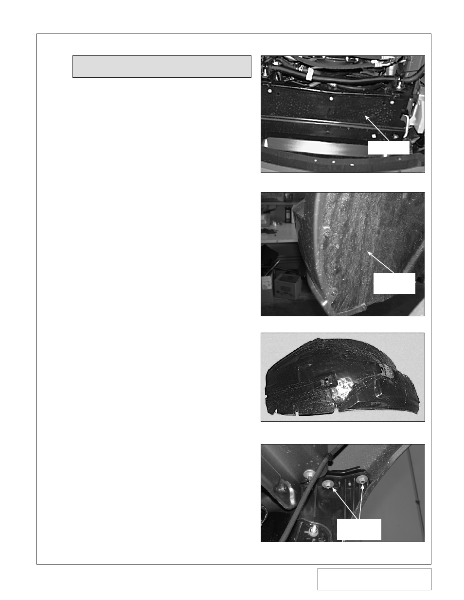
BUMPER COVER AND SPLASH PAN
1.
Raise the vehicle with a floor jack and set on
jack stands.
2.
Remove the seven 5.5mm headed screws
retaining the lower splash panel. (See Fig.
8A-a.)
3.
Remove the six Phillips-head screws (three
on each side) from the lower portions of the
plastic innner fender liners. (See Fig. 8A-b.).
On
2010 Models, remove the four 7mm head-
ed screws (2 per side) from the lower portions
of the plastic inner fender liner.
4.
Remove the five plastic clips retaining the
front portion of the fender liner. Both sides
need to be removed. (See Fig. 8A-c.)
5.
Remove the four 10mm nuts (two on each
side) retaining the bumper cover to the fend-
ers. (See Fig. 8A-d.)
2010 models do not use the bracket depicted
in Fig.8A-d. Pull outward from rear most por-
tion of the bumper where it attaches to the
inner fender to unsnap from retainers. The
bumper detaches along the bumper to fender
body line and underneath the headlights.
8. CHARGE AIR COOLER INSTALLATION
(CHARGE COOLED KITS ONLY)
Fig. 8A-a
Fig. 8A-b
Fig. 8A-c
Fig. 8A-d
10mm
HEADED
BOLTS
NOTE: For non-cooled kits skip this section
and proceed to Section 9.
SPLASH
PANEL
INNER
FENDER
LINER