2 supercharger mounting plate installation – Vortech 2005-2010 Ford 4.6L 3v Mustang GT User Manual
Page 40
P/N: 4FU020-010 v6.2, 06-08-10
©2010 Vortech Engineering, LLC
All Rights Reserved, Intl. Corp. Secured
18
A.
The mounting plate is provided with the spacers and
bolts as they would be installed on the vehicle. Keep
these bolts and spacers marked as to their loca-
tions. They are all different in size and mismatching
them will result is misalignment of the mounting
plate.
B.
(Non V-Power/Bullitt Kits only) Locate the two sup-
plied stud-bolt spacers (see Figs. 6.2-b, 6.2-c) in the
S/C mounting plate assembly. Remove the factory
screws retaining the idler pulleys on the driver’s side of
the engine and replace with the stud spacers.
C.
It is necessary to install the supercharger acces-
sory drive belt and loosely route it following Fig.
6.2-c, as not all pulleys are currently in place.
D.
Locate the supercharger mounting plate 4FU010-
044 from the supercharger mounting plate assem-
bly. (See Fig. 6.2-a.)
E.
(Non V-Power/Bullitt Kits only) Locate the two 8mm
x 140mm long bolts and washers from the mount-
ing bracket assembly and install in the locations
noted. (See Fig. 6.2-a.)
F.
Slide the two long spacers onto the bolts previ-
ously installed. (See Fig. 6-f.) Install the small tri-
angle-shaped idler pulley mounting bracket to the
spacers. Install the .093" spacer onto the bolt that
will be attached in the alternator location.
G.
Lower the mounting plate assembly into position on
the front of the engine. Be sure to route the drive
belt on the correct side of the idler bracket and spac-
ers. (See Fig. 6.2-g.)
H.
Loosely attach the plate using the previously
installed 140mm hardware. Locate the two 3/8-16
x 1.0" bolts and washers and install through the
plate into the two stud bolt spacers retaining the
factory idlers. (See Figs. 6.2-a, 6.2-c.)
I.
Locate the 8mm x 150mm bolt and washer.
Loosely install the bolt through the mounting plate
and remaining long spacer into the engine cover
using Fig. 6.2-a for location reference.
J.
(Non V-Power/Bullitt Kits only) Locate the supplied
idler, 1.776" idler spacer, idler pilot spacer, 3/8-16
x 3.75" long bolt and washer. Install the bolt/wash-
er through the mounting plate, 1.776" spacer, sup-
plied idler, idler pilot spacer and into the triangle-
shaped bracket. (See Figs. 6.2-f to 6.2-h for
assistance.)
6.2 SUPERCHARGER MOUNTING PLATE INSTALLATION
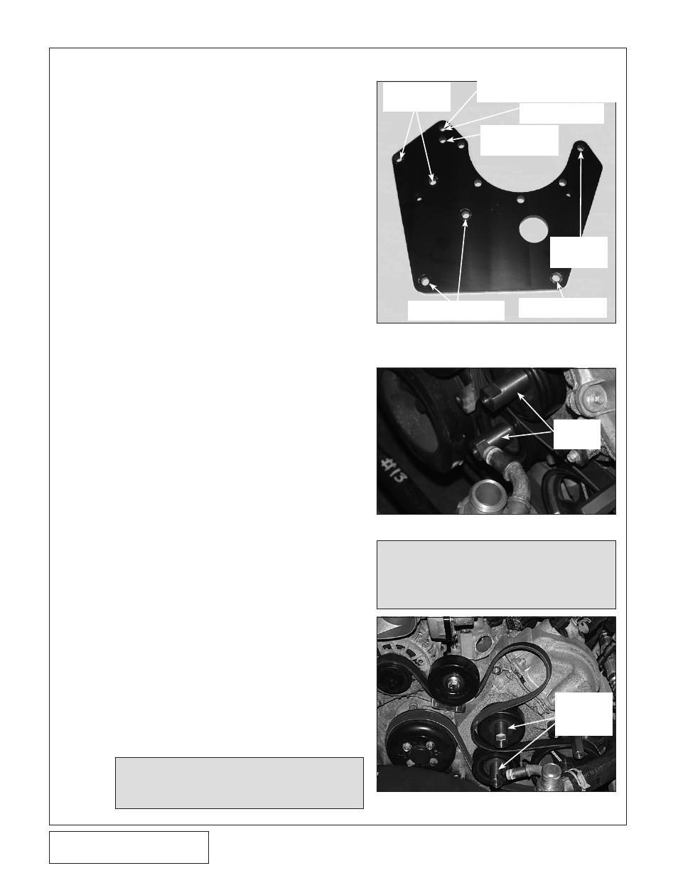
Fig. 6.2-a 2005-2008 NON-COOLED & 2010
H.O. MODEL IDLER LOCATION
Fig. 6.2-b
Fig. 6.2-c
NOTE: If installing a standard output kit (non-
cooled), the 3/8" x 3.75" bolt will be
installed in the upper hole location. H.O.
kits install in the lower hole.
2 x 8mm x
140mm
SCREWS
3/8-16 x 3.75"
SCREW
H.O. KIT SCREW
LOCATION
(NOT FOR 2010)
5 x 3/8-16
x 1.0"
SCREWS
NOTE: This figure is just for reference.
The small idler pulley mounting
bracket will need to be installed at
the same time as the supercharger
(S/C) Mounting Plate. (See Fig.
7-d.)
STUD
BOLT
SPACERS
STUD
BOLT
SPACERS
INSTALLED
2005-2008 NON-COOLED & 2010
H.O. MODEL IDLER LOCATION
8mm x 150mm
SCREW
2 x 3/8-16 x 1.0"
SCREWS