Management network settings, Management network – Ubiquiti Networks PowerBridgM User Manual
Page 31
28
Chapter 5: Network Tab
airOS
™
v5.5.4 User Guide
Ubiquiti Networks, Inc.
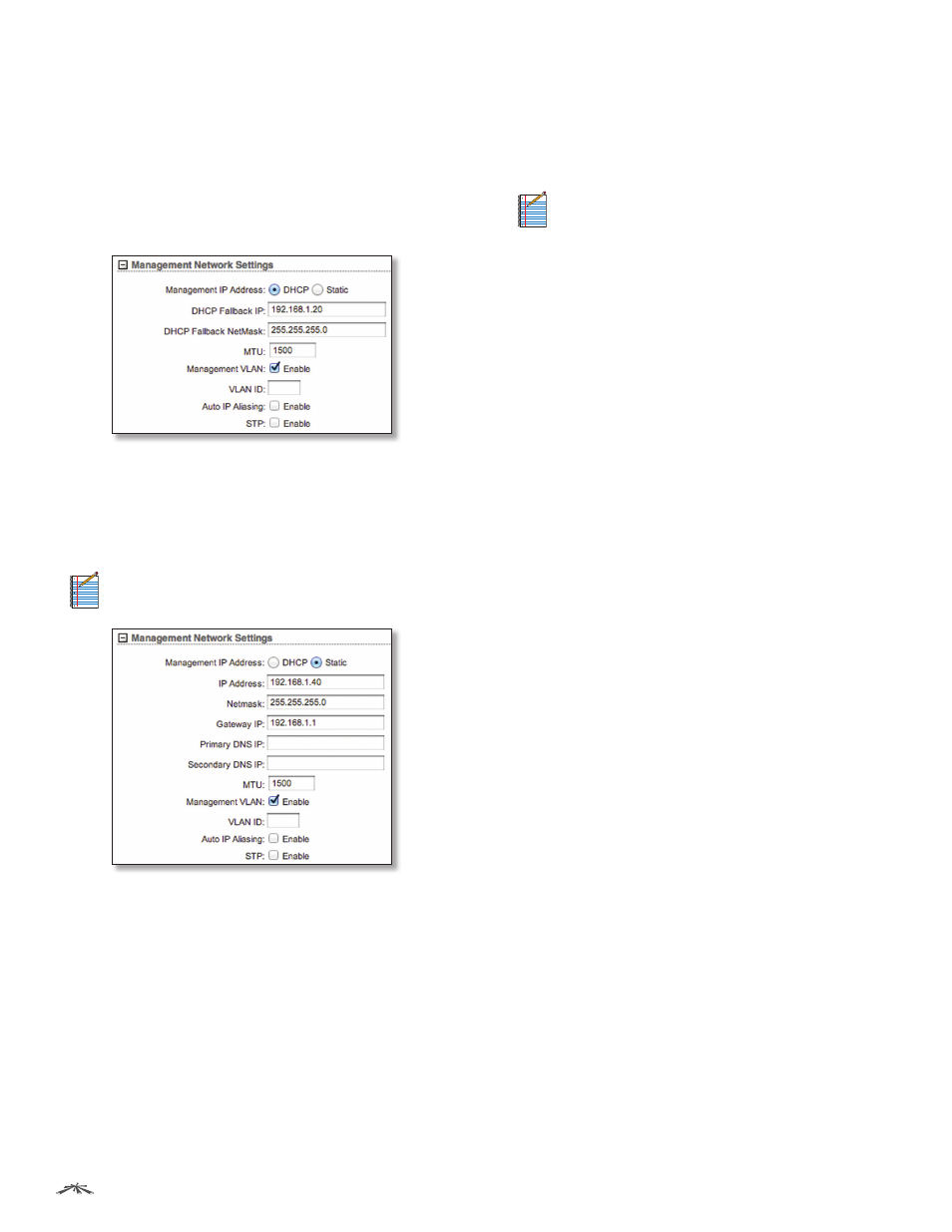
Management Network Settings
Management Interface
(Available in Advanced view.)
Select the interface used for management.
Management IP Address
The device can use a static IP
address or obtain an IP address from its DHCP server.
•
DHCP
The local DHCP server assigns a dynamic IP
address, gateway IP address, and DNS address to the
device.
-
DHCP Fallback IP
Specify the IP address for the
device to use if a DHCP server is not found.
-
DHCP Fallback Netmask
Specify the netmask for the
device to use if a DHCP server is not found.
•
Static
Assign static IP settings to the device.
Note:
IP settings should be consistent with the
address space of the device’s network segment.
-
IP Address
Specify the IP address of the device. This
IP will be used for device management purposes.
-
Netmask
When the netmask is expanded into its
binary form, it provides a mapping to define which
portions of the IP address range are used for the
network devices and which portions are used for host
devices. The netmask defines the address space of
the device’s network segment. The 255.255.255.0 (or
“/24”) netmask is commonly used on many Class C IP
networks.
-
Gateway IP
Typically, this is the IP address of the host
router, which provides the point of connection to the
Internet. This can be a DSL modem, cable modem, or
WISP gateway router. The device directs data packets
to the gateway if the destination host is not within the
local network.
Note:
In Bridge mode, the gateway IP address
should be from the same address space (on the
same network segment) as the device.
-
Primary DNS IP
Specify the IP address of the primary
DNS (Domain Name System) server.
-
Secondary DNS
Specify the IP address of the
secondary DNS server. This entry is optional and used
only if the primary DNS server is not responding.
MTU
(Available in Simple view.) The Maximum
Transmission Unit (MTU) is the maximum packet size (in
bytes) that a network can transmit. The default is 1500.
Management VLAN
(Available in Simple view.) If enabled,
automatically creates a management Virtual Local Area
Network (VLAN).
•
VLAN ID
Enter a unique VLAN ID from 2 to 4094.
Auto IP Aliasing
If enabled, automatically generates an
IP address for the corresponding WLAN/LAN interface.
The generated IP address is a unique Class B IP address
from the 169.254.X.Y range (netmask 255.255.0.0), which
is intended for use within the same network segment only.
The Auto IP always starts with 169.254.X.Y, with X and Y
as the last two octets from the MAC address of the device.
For example, if the MAC is 00:15:6D:A3:04:FB, then the
generated unique Auto IP will be 169.254.4.251.
The Auto IP Aliasing setting can be useful because you
can still access and manage devices even if you lose,
misconfigure, or forget their IP addresses. Because an
Auto IP address is based on the last two octets of the MAC
address, you can determine the IP address of a device if
you know its MAC address.
STP
Multiple interconnected bridges create larger
networks using IEEE 802.1d Spanning Tree Protocol
(STP), which is used for finding the shortest path within a
network and eliminating loops from the topology.
If enabled, the device bridge communicates with other
network devices by sending and receiving Bridge Protocol
Data Units (BPDU). STP should be disabled (default setting)
when the device is the only bridge on the LAN or when
there are no loops in the topology, as there is no need for
the bridge to use STP in this case.