Spectrum Controls 1734sc-IE2CH User Manual
Page 40
3-18
Point IO™ 2/4 Channel Analog HART Module
User’s Manual Pub. 0300257-01 Rev. A
ANALOG STATUS BITS:
CF = Channel Fault status; 0 = no error, 1 = fault
CM = Calibration Mode; 0 = normal, 1 = calibration mode
LA = Low Alarm; 0 = no error, 1 = fault
HA = High Alarm; 0 = no error, 1 = fault
LLA = Low/Low Alarm; 0 = no error, 1 = fault
HHA = High/High Alarm; 0 = no error, 1 = fault
UR = Underrange; 0 = no error, 1 = fault
OR = Overrange; 0 = no error, 1 = fault
HART STATUS BITS:
INIT = HART device detected
FAIL = No device found or communication failed
MAFLT = HART does not match analog loop current
MSGRDY = Ladder pass-through message available
DDLDR = Device Data update Ladder
(New HART Device Information Available see page 4-6)
DDLGX = Device Data update Logix (Reserved – Not Used)
SUA = Status Update Available, Cmd48 data changed
FAULT= HART device reports a fault
1
See page # B-2 for more information.
2
See page # B-2 for more information.
3
This is the first byte returned by HART command 9 when HART version 6 or 7 is used.
0x04 = Critical Power Failure, 0x02 = Device Variable Alert, 0x01 = Maintenance Required
Section 3.7
Module
Update Time
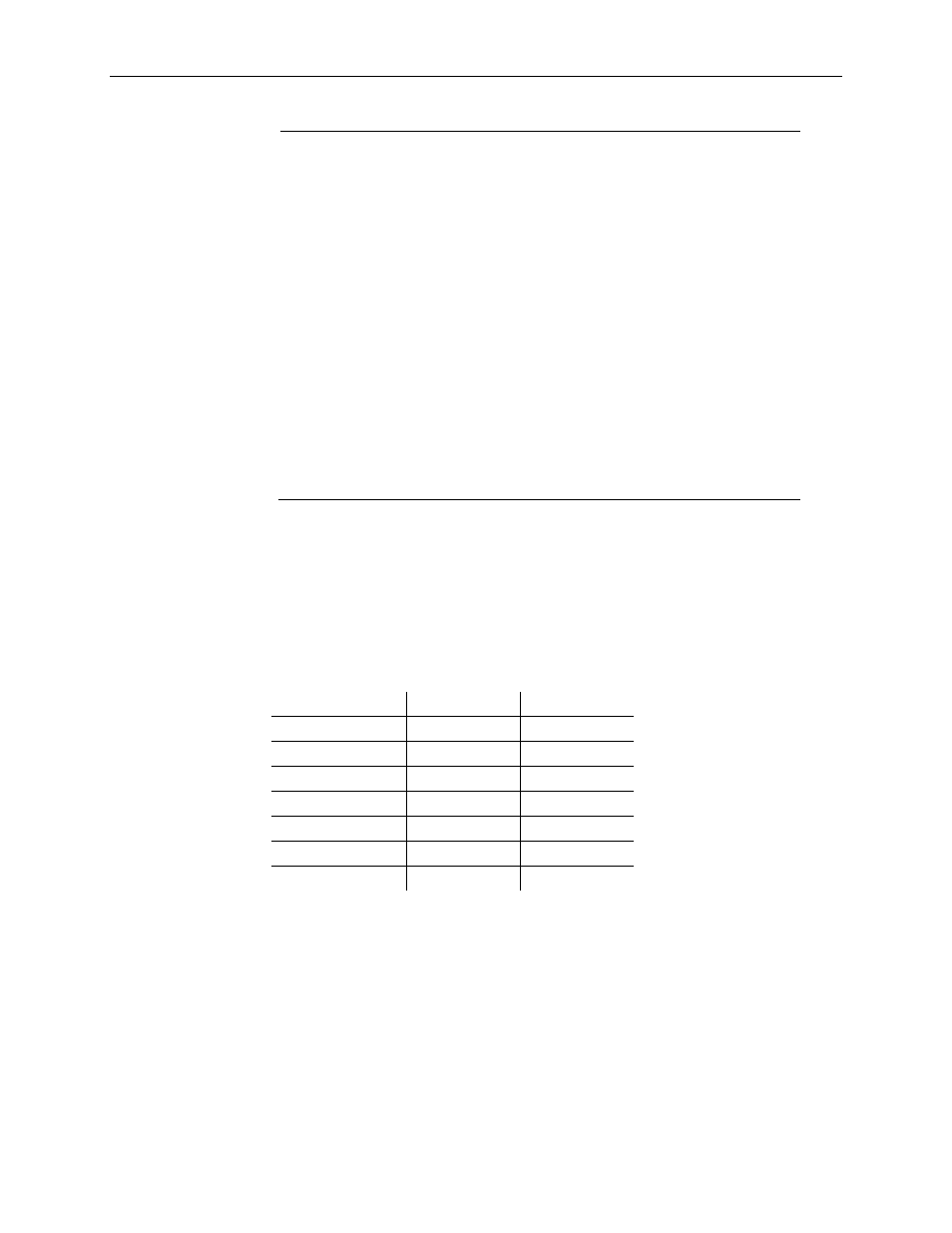
The module update time is determined by the number of input channels enabled and by
the filter frequency selected for each channel.
Table 3-6 (Module Update Time)
Filter Frequency
1734sc-IE2CH 1734sc-IE4CH
50/60 Hz (Default)
488 ms
248 ms
50 Hz
248 ms
128 ms
60 Hz
208 ms
108 ms
100 Hz
128 ms
68 ms
120 Hz
108 ms
58 ms
240 Hz
58 ms
33 ms
480 Hz
33 ms
21 ms