Spectrum Controls 1734sc-IE2CH User Manual
Page 32
3-10
Point IO™ 2/4 Channel Analog HART Module
User’s Manual Pub. 0300257-01 Rev. A
Generic Module Profile:
[Name of remote communication module]:e:x.Data[0 to 198]
e = IExCH slot number
x = Image Type (i.e. C, I, or O)
AOP (Add-On-Profile):
[Name of remote communication module]:e:x
e = IE4CH slot number
x = Image Type (i.e. C, I, or O)
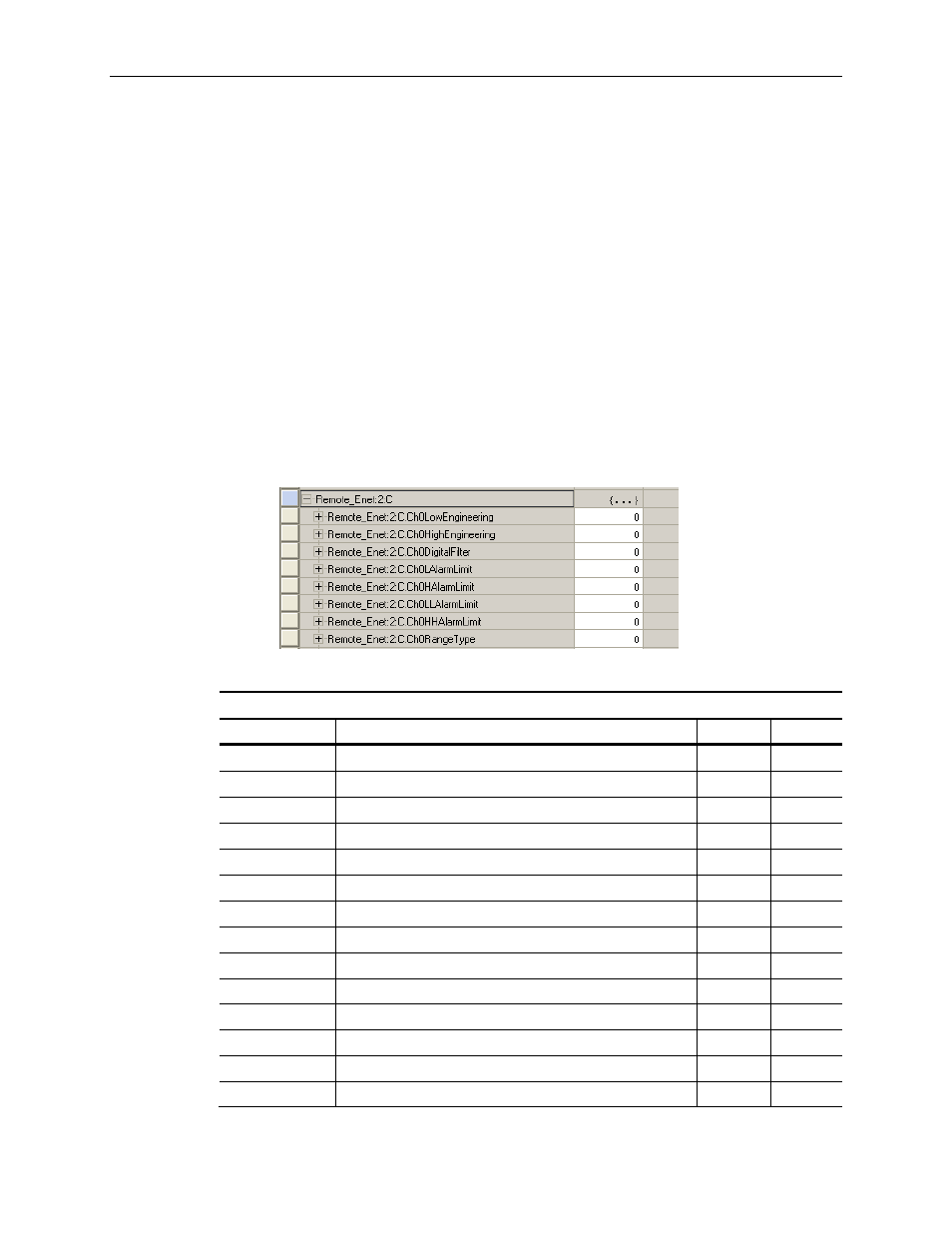
Note: The AOP will provide a predefined tag structure for the
configuration. See example below.
Figure 3-1 (AOP Config. Tags)
Table 3-1 (IE2CH Configuration Assembly)
Instance: 225
Size: 50 Bytes (DNET 46 Bytes)
OFFSET
FIELD
TYPE
BYTES
0x00 – 0x11
Channel 1 Configuration
STRUCT
20
+0x00
Low Engineering Channel 0
INT 2
+0x02
High Engineering Channel 0
INT 2
+0x04
Digital Filter Channel 0
INT 2
+0x06
Low Alarm Channel 0
INT 2
+0x08
High Alarm Channel 0
INT 2
+0x0A
Low Low Alarm Channel 0
INT 2
+0x0C
High High Alarm Channel 0
INT 2
+0x0E
Reserved pad alignment bytes
SINT 1
+0x0F
Alarm Latch Channel 0
SINT 1
+0x10
Enable Hart Channel 0
SINT 1
+0x11
Alarm Disable Channel 0
SINT 1
+0x12
Reserved pad alignment bytes
INT 2
0x14
Channel 1 Configuration
STRUCT
20