Spectrum Controls 1734sc-IE2CH User Manual
Page 37
Chapter 3: Configuring the 1734sc-IExCH for RSLogix 5000
3-15
User’s Manual Pub. 0300257-01 Rev. A
Table 3-4 (IE2CH Input Assembly)
Instance:
104
100
101
102
103
Description:
Analog + Hart 0,1
Analog Only
Analog + Hart 0
Analog + Hart 0, 1
Analog + Hart 0, 1
Total Size:
60 Bytes RSL5K (DNet 56 bytes)
12 Bytes RSL5K (Dnet 8 bytes)
36 Bytes RSL5K (Dnet 32 bytes)
60 Bytes RSL5K (Dnet 56 bytes)
60 Bytes RSL5K (Dnet 56 bytes)
( instance 104 is the default, instances 100-101 are subsets available to conserve bandwidth,
instances 102,103 are redundant included for code compatibility between 2 and 4 ch )
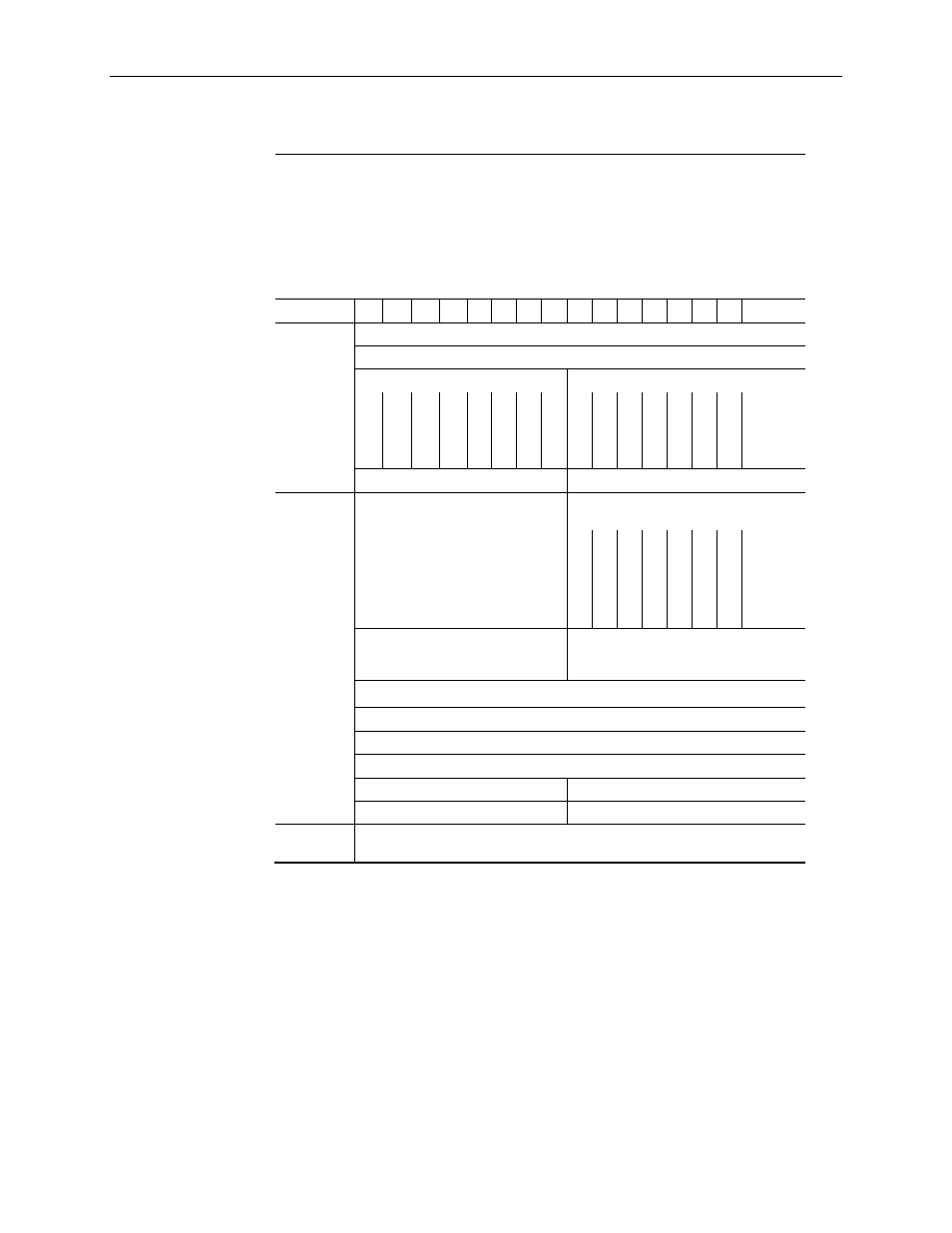
Bit
15 14 13 12 11 10 09 08 07 06 05 04 03 02 01
00
Analog data
8 bytes
0x00-0x07
Channel 0 Data - INT
Channel 1 Data - INT
Status Byte for Channel 1
Status Byte for Channel 0
OR
UR
HHA
LLA
HA
LA
CM
CF
OR
UR
HHA
LLA
HA
LA
CM
CF
Reserved alignment pad byte - SINT Reserved alignment pad byte - SINT
Ch. 0 Hart
Data
24 bytes
0x08-0x1F
Input Ch 0 Hart Device Status Byte
1
Input Ch0 Hart Device Status Byte 0
Response Code
1
FAU
L
T
SU
A
DDLGX
DDLDR
M
S
GRDY
MAFL
T
FAIL
IN
IT
Input Ch 0 Hart Device Status Byte
3
Extended Device Status Byte
3
Input Ch 0 Hart Device Status Byte 2
Field Device Status Byte
2
Input Channel 0 Hart PV - REAL (float)
Input Channel 0 Hart SV - REAL (float)
Input Channel 0 Hart TV - REAL (float)
Input Channel 0 Hart FV - REAL (float)
Input Channel 0 Hart SV Status
Input Channel 0 Hart PV Status
Input Channel 0 Hart FV Status
Input Channel 0 Hart TV Status
Ch .1 Hart
0x20-0x38
(Data structure same as channel 0 above, 24 bytes)