Experiment #49: audio and, nand – Elenco Basic Electronic Experiments User Manual
Page 66
66
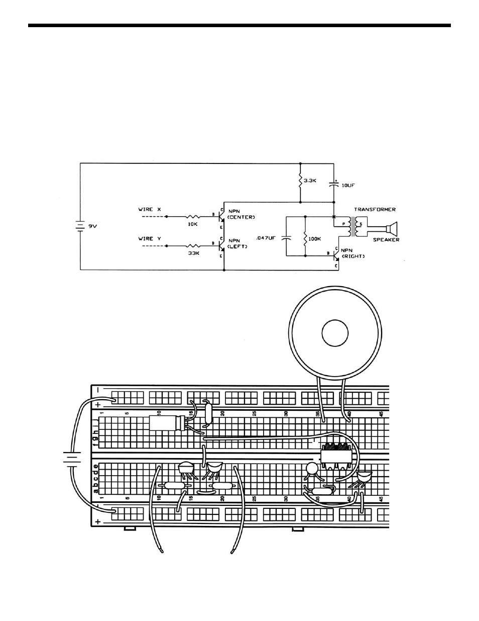
EXPERIMENT #49: AUDIO AND, NAND
Using the LEDs for these truth tables probably seems a little boring. So let’s use an audio circuit to make a sound instead
of turning on the LED. Connect the wires according to the schematic and Wiring Diagram. Can you tell which digital gate
this circuit represents? Construct the truth table to find out.
It is the NAND gate. If you use longer wires for X and Y and leave them connected HIGH then you have an alarm with two
separate trip wires.
You can easily modify the circuit to be an AND gate. Remove the 3.3k
Ω resistor, the 10μF capacitor, and wires e17-to-f17,
g17-to-c38, and a42-to-(–)42. Add wires a42-to-e17 and c38-to-(+)30. This audio circuit can also be used with the OR
and NOR gates simply by rewiring NPN-left, NPN-center, and the 10k
Ω, 33kΩ resistors.
+9V
10
μF
33k
Ω
S
P
473
3.3k
Ω
100k
Ω
10k
Ω
WIRE X
WIRE Y