Experiment #26: the anti-capacitor – Elenco Basic Electronic Experiments User Manual
Page 39
39
EXPERIMENT #26: THE ANTI-CAPACITOR
Recall that capacitors blocked direct current (DC) but passed alternating current (AC). Take a look at Experiment 8 again
and remember that it took time to light the LED because you had to charge the capacitor first; the capacitor passed the
initial current surge through to ground (the negative side of the battery) but blocked the current once it stabilized, forcing it
to go through the LED. The inductor is the counterpart to this - it blocks current surges (AC) but passes stable currents
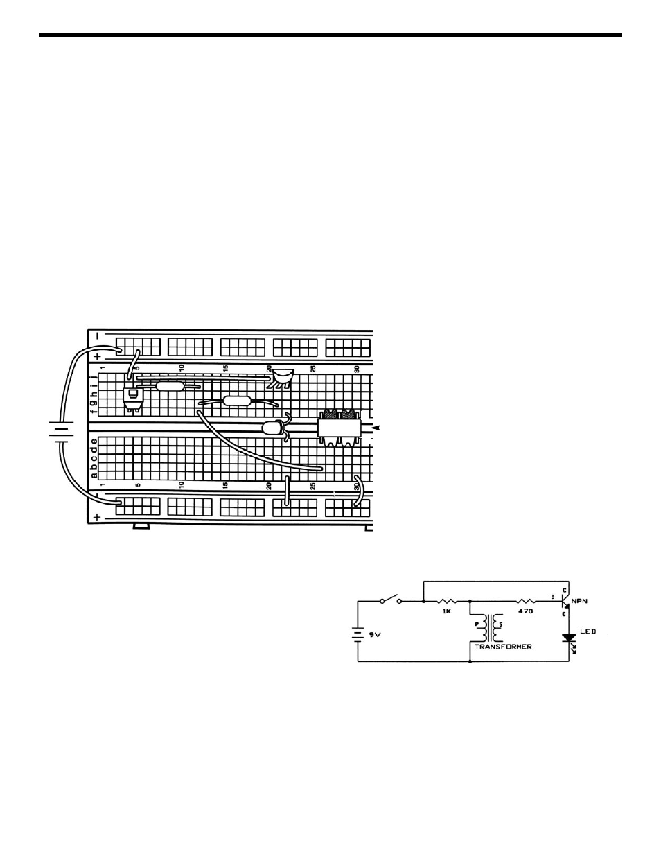
(DC). Before explaining the inductor further, let’s demonstrate it using almost the same circuit as in Experiment 8.
We will be using an inductor that is part of the transformer, we’ll explain more about this later. Connect the circuit and press
the switch several times. The LED will blink once when the switch is pressed. Note how this is different from the capacitor,
when the LED became bright when the switch was pressed and stayed bright until the switch was released. The inductor
effects are brief, so we are using the transistor to amplify the current to the LED and make the inductor’s effects easier to
see.
Now remove the wire from hole b26 (on the transformer), connect it to hole b28, and press the switch a few more times.
The LED will not blink as brightly now, because we are using less inductance.
+9V
470
Ω
1k
Ω
TRANSFORMER
(Primary side has 3
wires while secondary
side has only 2 wires.
The primary goes in
holes e26, e28, and e30
while the secondary
goes into f26 and f30.)
S
P