Elenco Basic Electronic Experiments User Manual
Page 19
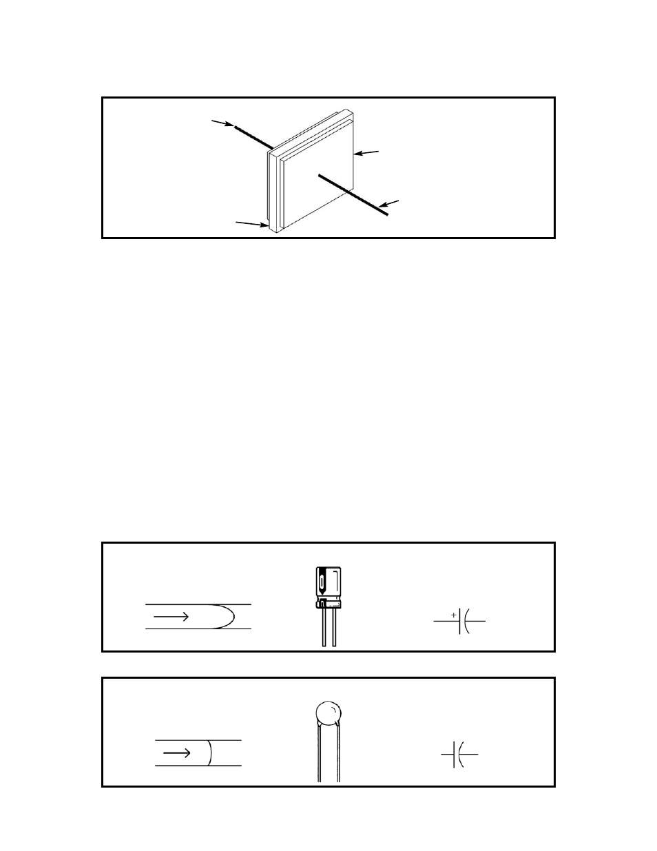
Similarly, capacitors are described by their capacity for holding electric charge, called their Capacitance, and their ability
to withstand electric pressure (voltage) without damage. Although there are many different types of capacitors made using
many different materials, their basic construction is the same. The wires (leads) connect to two or more metal plates that
are separated by high resistance materials called dielectrics.
The dielectric is the material that holds the electric charge (pressure), just like the rubber diaphragm holds the water
pressure. Some dielectrics may be thought of as stiff rubber, and some as soft rubber. The capacitance and working
voltage of the capacitor is controlled by varying the number and size of metal-dielectric layers, the thickness of the dielectric
layers, and the type of dielectric material used.
Capacitance is expressed in farads (F, named after Michael Faraday whose work in electromagnetic induction led to the
development of today’s electric motors and generators ), or more commonly in microfarads (
μF, millionths of a farad) or
picofarads (pF, millionths of a microfarad). Almost all capacitors used in electronics vary from 1pF to 1,000
μF.
Your PK-101 includes two electrolytic (10
μF and 100μF) and two disc (0.005μF and 0.047μF) capacitors. (Mylar capacitors
may have been substituted for the disc ones, their construction and performance is similar). Electrolytic capacitors (usually
referred to as lytics) are high capacitance and are used mostly in power supply or low frequency circuits. Their capacitance
and voltage are usually clearly marked on them. Note that these parts have “+” and “–” polarity (orientation) markings, the
lead marked “+” should always be connected to a higher voltage than the “–” lead (all of your Wiring Diagrams account for this).
Disc capacitors are low capacitance and are used mostly in radio or high frequency applications. They don’t have polarity
markings (they can be hooked up either way) and their voltage is marked with a letter code (most are 50V). Their value is
usually marked in pF with a 3 digit code similar to the stripes used on resistors. The first 2 digits are the first 2 digits of the
capacitor’s value and the third digit tells the power of 10 to multiply by (or the number of zeros to add). For example, the
0.005
μF (5,000pF) and .047μF (47,000pF) disc capacitors in your PK-101 are marked 502 and 473.
Capacitors have symbols as follows:
19
DIELECTRIC
METAL PLATE
LEAD 2
LEAD 1
Construction
of a Capacitor
SOFT DIAPHRAGM
STIFF DIAPHRAGM
ELECTROLYTIC CAPACITOR
DISC CAPACITOR
Symbol for
DISC CAPACITOR
Symbol for
ELECTROLYTIC CAPACITOR
(–) (+)