Experiment 5: comparison of parallel currents – Elenco Basic Electronic Experiments User Manual
Page 15
15
EXPERIMENT 5: COMPARISON OF PARALLEL CURRENTS
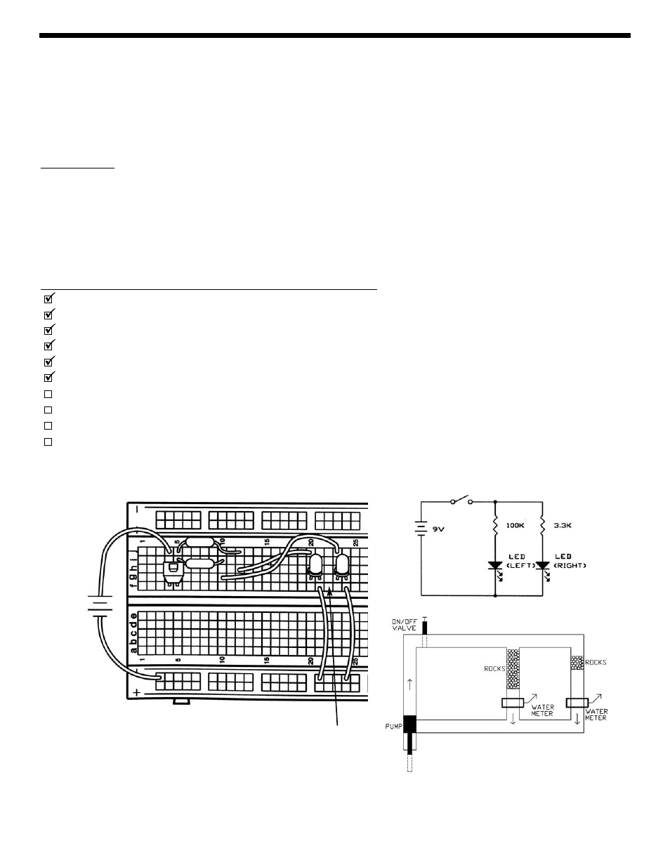
Since we have two resistors in parallel and a second LED that is not being used, let’s modify the last circuit to match the
schematic below. It’s basically the same circuit but instead of just parallel resistors there are parallel resistor-LED circuits.
Remove the resistors used in Experiment #4; the other parts are used here. Insert the new parts according to the Wiring
Checklist. Replace the 100k
Ω resistor with several values as before (such as 1kΩ, 10kΩ, and others if you wish), pressing
the switch and observing the LEDs each time. The brightness of the right LED will not change, but the brightness of the
left LED will depend on the resistor value you placed in series with it.
Parts Needed:
• a 9V battery or power supply
• Switch
• one 3.3k
Ω resistor (orange-orange-red-gold)
• one 100k
Ω resistor (brown-black-yellow-gold)
• 2 LEDs
• 4 wires
Wiring Checklist (
þ indicates same position as last experiment):
Insert red battery wire or positive P. S. into j4 and black battery wire or negative P. S. (ground) into (–)3.
Insert switch into f4 and f5. The switch may be a tight fit, carefully press it in slowly.
Insert an LED into g20 and g21 (“flat” side goes into g21).
Insert a short wire between f21 and (–)21.
Insert the 100k
Ω resistor into j5 and j12.
Insert a short wire between h12 and j20.
Insert the 3.3k
Ω resistor into i5 and j10.
Insert a short wire between g10 and j23.
Insert an LED into g23 and g24 (“flat” side goes into g24).
Insert a short wire between f24 and (–)24.
+9V
3.3k
Ω
100k
Ω
9V
BATTERY
or POWER
SUPPLY
Both LEDs
have flat side
on right