Experiment #20: the two finger touch lamp, Experiment #19: the darlington – Elenco Basic Electronic Experiments User Manual
Page 32
32
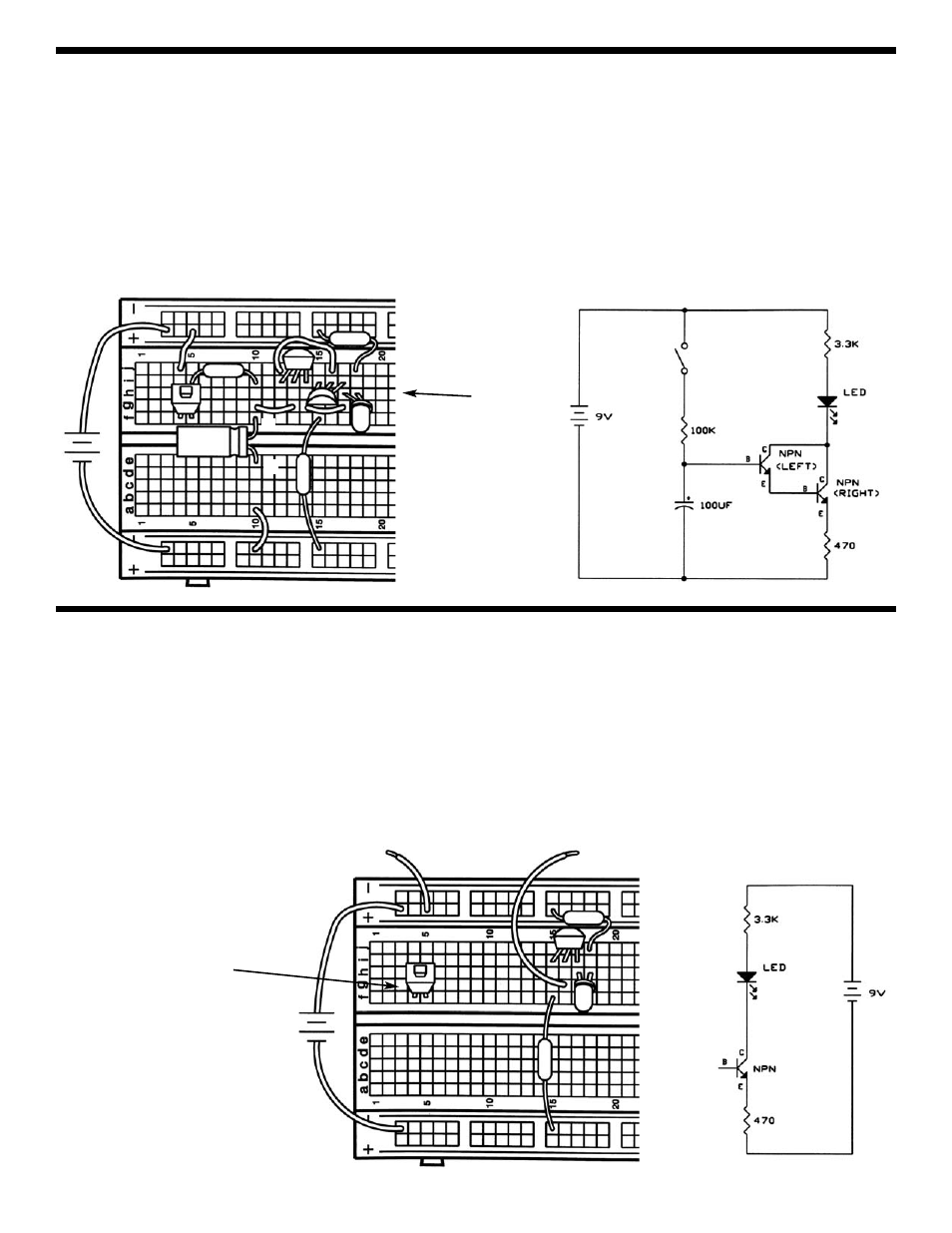
EXPERIMENT #20: THE TWO FINGER TOUCH LAMP
Take a look at the schematic. You’re probably wondering how it can work, since nothing is connected to the transistor base.
It can’t, but there is another component that isn’t shown in the schematic. That component is you.
Connect the circuit according to the schematic and Wiring Diagram, including the two loose wires. Now touch the loose
battery wire with one finger and the loose transistor wire with another. The LED may be dimly lit. The problem is your
fingers aren’t making good enough electrical contact with the springs. Wet your fingers with water or saliva and touch the
springs again. The LED should be very bright now. You saw in Experiment 7 how water can conduct electricity and since
your body is mostly water it shouldn’t surprise you that your body can also conduct. Your body’s resistance varies a lot,
but is typically a few hundred kilohms. Think of this circuit as a touch lamp since when you touch it the LED lights. You
may have seen such a lamp in the store or already have one in your home.
(LOOSE WIRE)
(LOOSE WIRE)
+9V
470
Ω
3.3k
Ω
(switch is left unconnected
for future experiments)
EXPERIMENT #19: THE DARLINGTON
This circuit is very similar to the last one. Connect the components and press the switch, hold it down for several seconds.
The LED will slowly light up. Release the switch and the LED stays lit.
Take a look at the schematic. All the current flowing through the emitter of the left transistor will flow to the base of the
right transistor. So the current flowing into the base of the left transistor will be amplified twice, once by each transistor.
This configuration is called the Darlington configuration. It has very high current gain and very high input resistance at
the base. Since there are now two transistors to turn on, the capacitor voltage must exceed 1.4V before the LED will start
to light. And, since the input current to the base is so small, it will take much longer to discharge the capacitor. But the
circuit is functionally the same as Experiment 18 and the LED will eventually go dark, though it may take a few minutes.
You can experiment with changing some of the component values if you like.
+9V
3.3k
Ω
100
μF
100k
Ω
470
Ω
(Note positions
of flat sides)
+
-