Experiment #48: this and that – Elenco Basic Electronic Experiments User Manual
Page 65
EXPERIMENT #48: THIS AND THAT
Take a look at the schematic. Can you guess what kind of digital gate this is? We’ll use almost the same circuit here as
in the last experiment. Remove the wire between holes a16 and a17, and the one between holes a19 and (–)19. Add a
wire between holes a16 and a19. Also, remove the 100k
Ω resistor, we’ll re-connect it later.
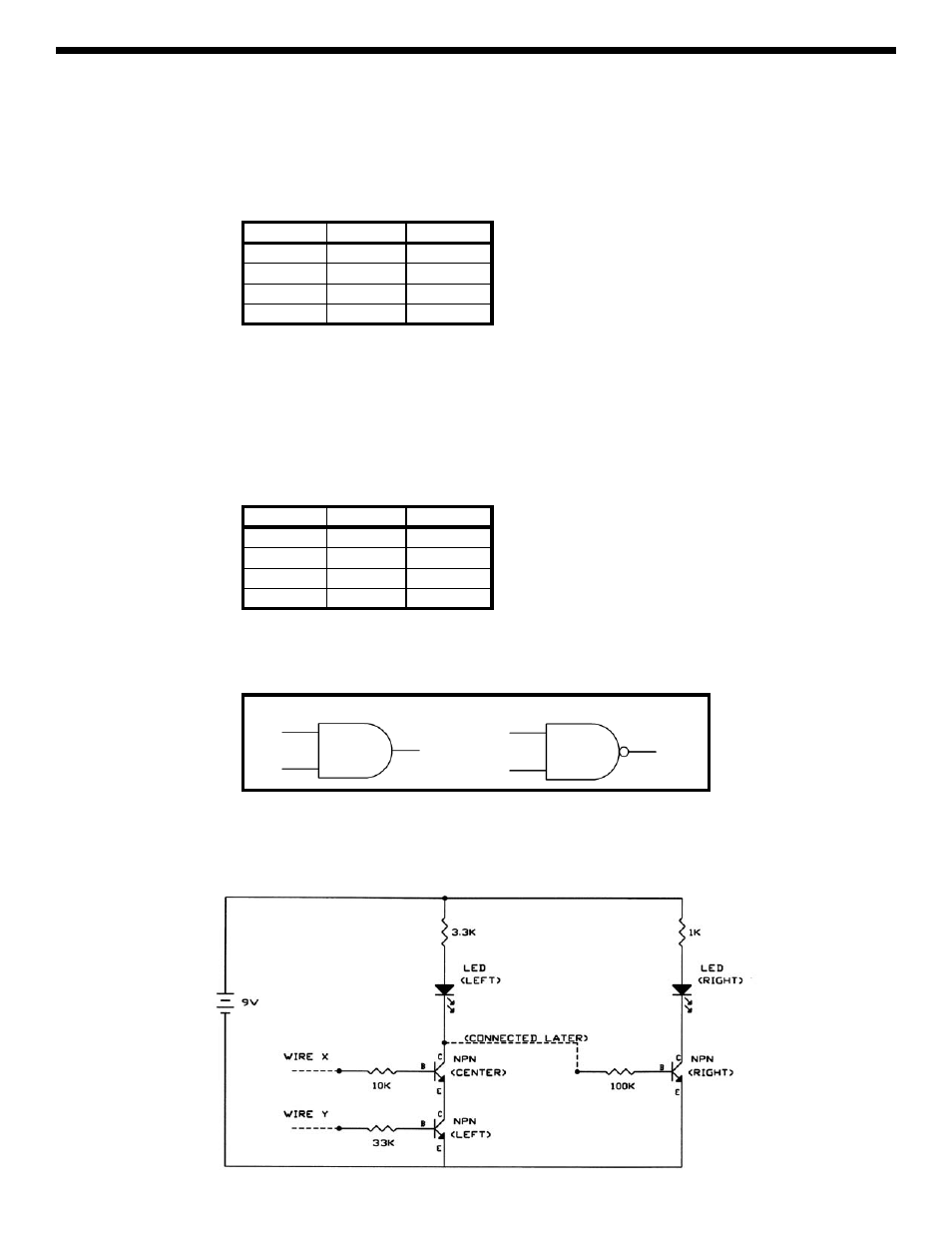
Test the four combinations of X and Y to determine the truth table:
X Y
LED-left
LOW LOW
LOW HIGH
HIGH LOW
HIGH HIGH
From it, you can see that if X
and Y are HIGH then LED-left will be ON. Hence, this configuration is called an AND gate.
X and Y might represent two switches to turn on the same light in your house, the room switch and the master switch in
the electrical box
. As with the gates we showed you earlier, you could have more than two inputs by just adding more parts
to the circuit.
Now place the 100k
Ω back into the circuit (between holes b24 and b27 as before), and look at LED-right. Since you are
just adding a NOT gate as you did in the last experiment you probably know what the new truth table will look like:
X Y
LED-right
LOW LOW
LOW HIGH
HIGH LOW
HIGH HIGH
It is a NAND gate, a combination of AND and NOT. X and Y might represent different trip wires for your burglar alarm (if
either is tripped then that input goes LOW and the alarm sounds). AND and NAND have the schematic symbols shown
below:
AND Gate
NAND Gate
Combinations of AND and OR gates are used to add and multiply numbers together in computers. The additional use of
NOT, NOR, and NAND gates allows a computer to represent any input/output pattern you can think of. By combining these
gates with the memory and timing control that flip-flops provide, today’s computers are created.
65