Experiment #27: the magnetic bridge – Elenco Basic Electronic Experiments User Manual
Page 42
42
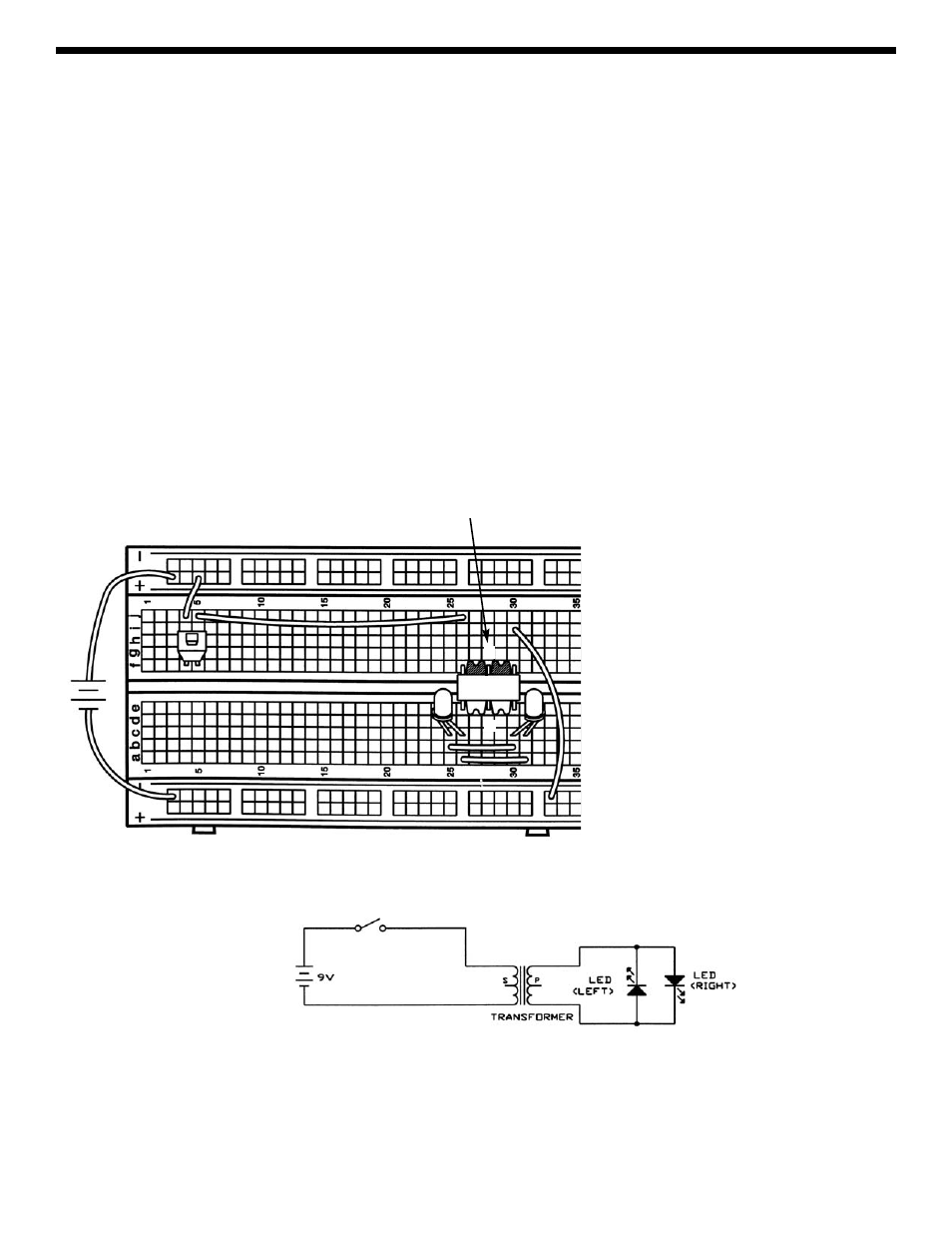
EXPERIMENT #27: THE MAGNETIC BRIDGE
Connect the circuit and press the switch several times. LED-left blinks when the switch is pressed and LED-right blinks
when the switch is released.
Although the LED may blink in the same manner as the last experiment, the method is quite different. There is no wire
connection across the transformer, its DC resistance is very high. When you press the switch there is a sudden surge of
current (AC) through the inductor that magnetically creates a current on the other side of the transformer, lighting LED-left.
The current from the battery quickly settles after the initial surge (becomes DC) and the magnetic induction stops because
the current is no longer changing, hence no current flows through the LED even though there is current on the battery side
of the transformer. When you release the switch the sudden drop in current through the transformer magnetically creates
a new current on the other side of the transformer, but this time in the opposite direction so LED-right lights instead of LED-
left. Again, this current is brief and the LED only blinks. The transformer has many more turns (more inductance) on the
LED side than on the battery side; this boosts the voltage to the LEDs (though it also lowers the current). If you reverse
the transformer then you won’t have enough voltage to turn on the LEDs.
You might think of a transformer as a magnetic bridge in electronics, since we use magnetism to cross a barrier that
electricity cannot cross by itself. Transformers are mainly used for isolating and buffering different circuits from each other,
and you will soon see some examples of this.
+9V
TRANSFORMER
(Primary side has 3
wires while secondary
side has only 2 wires.
S
P
(Note positions
of LED flat sides)