Experiment #22: the voltmeter – Elenco Basic Electronic Experiments User Manual
Page 34
EXPERIMENT #22: THE VOLTMETER
Make sure you have a strong 9V battery for this experiment. Connect the circuit according to the Wiring Diagram and
schematic, connect the battery last since this will turn on the circuit. And be sure to disconnect the battery (or turn off your
power supply) when you’re not using the circuit to avoid draining the battery. The part of the circuit to the left of the dashed
line in the schematic is the voltmeter, the two resistors on the right produce a voltage that you will measure. Notice that
the variable resistor (VR) will always act as a 50k
Ω across the battery but by turning its knob you adjust the voltage at the
base of the left transistor. By turning this knob you can make one LED brighter than the other, indicating that the voltages
at the bases of the two transistors are not equal. Adjust the VR so that the two LEDs are equally bright. The transistor
base voltages are now equal. To determine what voltage you have measured, simply subtract the percentage you turned
your VR dial from 100 and multiply by 0.09.
If you like you can calculate what voltage you should have measured. Your measurement may differ from this due to the
tolerances in the resistors and the VR dial, but you should be close. The resistors on the right are a voltage adjuster, just
like the VR is, and the voltage you measured (at the base of the right transistor) is:
R
Lower
33k
Ω
V
Calculated
= ————————— x V
Battery
= ———————— x 9V = 6.9V
R
Upper
+ R
Lower
10k
Ω + 33kΩ
This circuit is a form of the Differential Pair transistor configuration, which is widely used in integrated circuits. If the
transistor base voltages are equal then the currents through the LEDs and collectors will also be equal. If one base voltage
is higher than the other then that transistor will have more current flowing through it’s collector and associated LED.
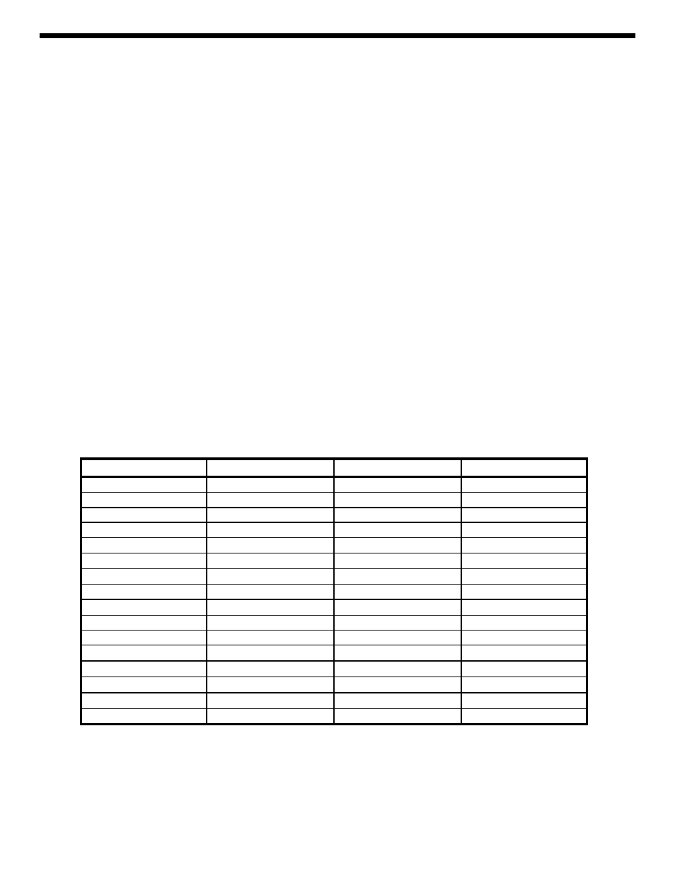
You can now replace the two resistors on the right with a different combination and make a new voltage measurement. The
table below lists different combinations of your PK-101 resistors that you can measure, but you don’t have to measure them
all. In some combinations resistors are placed in series or parallel to create new values.
Remember to disconnect the battery when you’re not using the circuit to avoid draining the battery.
Upper Resistor
Lower Resistor
Measured Voltage
Calculated Voltage
10k
Ω
33k
Ω
6.9V
33k
Ω
10k
Ω
2.1
33k
Ω
100k
Ω
6.8
100k
Ω
33k
Ω
2.2
3.3k
Ω
10k
Ω
6.8
10k
Ω
3.3k
Ω
2.2
1k
Ω
3.3k
Ω
6.90
3.3k
Ω
1k
Ω
2.1
10k
Ω
parallel 33k
Ω, 100kΩ
6.4V
parallel 33k
Ω, 100kΩ
10k
Ω
2.6V
series 10k
Ω, 33kΩ
100k
Ω
6.3
100k
Ω
series 10k
Ω, 33kΩ
2.7
1k
Ω
parallel 3.3k
Ω, 10kΩ
6.4
parallel 3.3k
Ω, 10kΩ
1k
Ω
2.6
series 1k
Ω, 3.3kΩ
10k
Ω
6.3
10k
Ω
series 1k
Ω, 3.3kΩ
2.7
34