Experiment #15: the current amplifier, Experiment #14: the electronic switch – Elenco Basic Electronic Experiments User Manual
Page 28
28
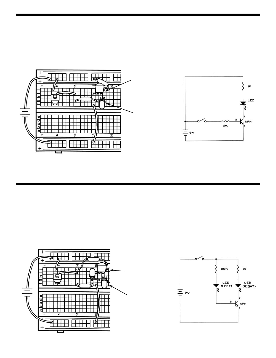
EXPERIMENT #15: THE CURRENT AMPLIFIER
Connect the circuit and press the switch. The right LED in the collector path is brighter than the left LED in the base path
because the base current is amplified by the transistor. The current gain of a transistor varies anywhere from 10 to 1,000
depending on the type of transistor, the ones in your PK-101 have a gain of about 200.
Note that the battery voltage and circuit resistance will limit the current gain. For example, if you replace the 1k
Ω in this
circuit with a 33k
Ω then the current gain will only be about 3. The circuit resistances, not transistor itself, are limiting the
current and the transistor is said to be saturated.
EXPERIMENT #14: THE ELECTRONIC SWITCH
Your PK-101 includes three transistors which are all type 2N3904 NPN Bipolar Junction Transistors. Connect the circuit
according to the schematic and Wiring Diagram. Although there is a closed circuit with the battery, 1k
Ω, LED, and
transistor, no current will flow since the transistor is acting like an open circuit (with no base current the lever arm remains
shut). Press the switch; a base current now flows and opens the lever arm, resulting in a large collector current which lights
the LED. The transistor is being used as an electronic switch. Although there is still a normal switch in this circuit, there
could be many electronic switches controlled by one normal switch.
+9V
10k
Ω
(flat side is
on left)
TRANSISTOR
(Note position
of flat side)
+9V
1k
Ω
(note how the
LED flat sides are
positioned)
TRANSISTOR
(Note position
of flat side)
100k
Ω
1kΩ