Experiment #6: combined circuit – Elenco Basic Electronic Experiments User Manual
Page 16
16
EXPERIMENT #6: COMBINED CIRCUIT
Let’s combine everything we’ve done so far. Remove the resistors used in Experiment #3; the other parts are used here.
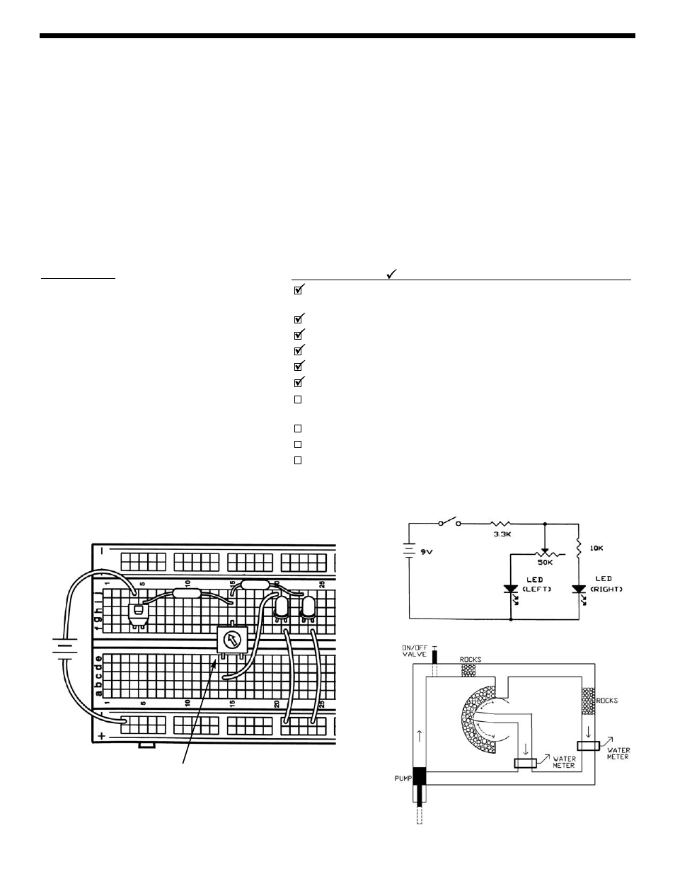
Insert the new parts and wires according to the Wiring Checklist. Before pressing the switch, take a look at the schematic
and think about what will happen as you turn the dial on the variable resistor (we’ll abbreviate this to VR). Now press the
switch with one hand and turn the dial with the other to see if you were right. As you turn the VR dial from left to right the
left LED will go from bright to very dim and the right LED will go from very dim to visible.
What’s happening is this: With the dial turned all the way to the left the VR is 0
Ω (much smaller than the 10kΩ) so nearly
all of the current passing through the 3.3k
Ω will take the VR-LED(left) path and very little will take the 10kΩ-LED(right) path.
When the VR dial is turned 1/5 to the right the VR is 10k
Ω (same as the other path) and the current flowing through the
3.3k
Ω will divide equally between the two LED paths (making them equally bright). As the VR dial is turned all the way to
the right the VR becomes a 50k
Ω (much larger than the 10kΩ) and LED(left) will become dim while LED(right) gets brighter.
Now is a good time to take notes on how resistors work in series and in parallel. All electronic circuits are much larger
combinations of series and parallel circuits such as these. It’s important to understand these ideas because soon we’ll
apply them to capacitors and inductors!
Parts Needed:
• a 9V battery or power supply
• Switch
• one 3.3k
Ω resistor (orange-orange-red-gold)
• one 10k
Ω resistor (brown-black-orange-gold)
• 50k
Ω variable resistor
• 2 LEDs
• 3 wires
Wiring Checklist ( indicates same position as last experiment):
Insert red battery wire or positive P. S. into j4 and black battery wire
or negative P. S. (ground) into (–)3.
Insert switch into f4 and f5.
Insert an LED into g20 and g21 (“flat” side goes into g21).
Insert a short wire between f21 and (–)21.
Insert an LED into g23 and g24 (“flat” side goes into g24).
Insert a short wire between f24 and -24.
Insert the 50k
Ω variable resistor into holes e14, g15, and e16. It
may be a tight fit, carefully press it in slowly.
Insert the 3.3k
Ω resistor into i5 and i15.
Insert the 10k
Ω resistor into j15 and j23.
Insert a short wire between c14 and j20.
+9V
3.3K
Ω
10K
Ω
50K
Ω
VARIABLE
RESISTOR