Experiment #4: parallel pipes – Elenco Basic Electronic Experiments User Manual
Page 14
14
EXPERIMENT #4: PARALLEL PIPES
Remove the resistors used in Experiment #3; the other parts are used here. Insert the new parts according to the Wiring
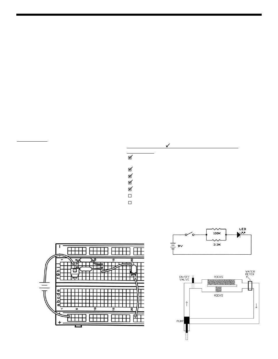
Checklist. Take a look at the schematic. There is a low 3.3k
Ω resistor and a high 100kΩ resistor in parallel (connected
between the same points in the circuit). How bright do you think the LED will be? Press the switch and see if you are right.
The LED is bright, so most of the current must be flowing through the smaller 3.3k
Ω resistor. This makes perfect sense
when we look at the water diagram, with most of the water flowing through the pipe with less rocks. In general, the more
water pipes (or resistors) there are in parallel, the lower the total resistance is and the more water (or current) will flow.
The relationship is more complicated than for resistors in series and is given here for advanced students:
R
1
x R
2
R
Parallel
=
______________
R
1
+ R
2
For two 10k
Ω resistors in parallel, the result would be 5kΩ. The 3.3kΩ and 100kΩ in parallel in our circuit now give the
same LED brightness as a single 3.2k
Ω resistor.
To demonstrate this, remove the 100k
Ω resistor and replace it with the 10kΩ (in the same holes); press the switch and the
LED should be just as bright. The total resistance is now only 2.5k
Ω, but your eyes probably won’t notice much difference
in LED brightness. Now remove the 10k
Ω and replace it with the 1kΩ; press the switch. The total resistance is now only
770
Ω, so the LED should now be much brighter.
Parts Needed:
• a 9V battery or power supply
• Switch
• one 1k
Ω resistor (brown-black-red-gold)
• one 3.3k
Ω resistor (orange-orange-red-gold)
• one 10k
Ω resistor (brown-black-orange-gold)
• one 100k
Ω resistor (brown-black-yellow-gold)
• one LED
• 2 wires
Wiring Checklist ( indicates same position as last
experiment):
Insert red battery wire or positive power supply (P. S.) into j4 and
black battery wire or negative power supply (ground) into (–)3.
Insert switch into f4 and f5.
Insert the LED into g20 and g21 (“flat” side goes into g21).
Insert a short wire between f21 and (–)21.
Insert the 3.3k
Ω resistor into i5 and i12.
Insert the 100k
Ω resistor into j5 and j12.
Insert a short wire between h12 and j20.
9V
BATTERY
or POWER
SUPPLY
+9V
0V
3.3K
Ω
WIRING DIAGRAM
100K
Ω
Note: From now on there will be less description for frequently used parts.