Experiment #47: neither this nor that – Elenco Basic Electronic Experiments User Manual
Page 64
64
EXPERIMENT #47: NEITHER THIS NOR THAT
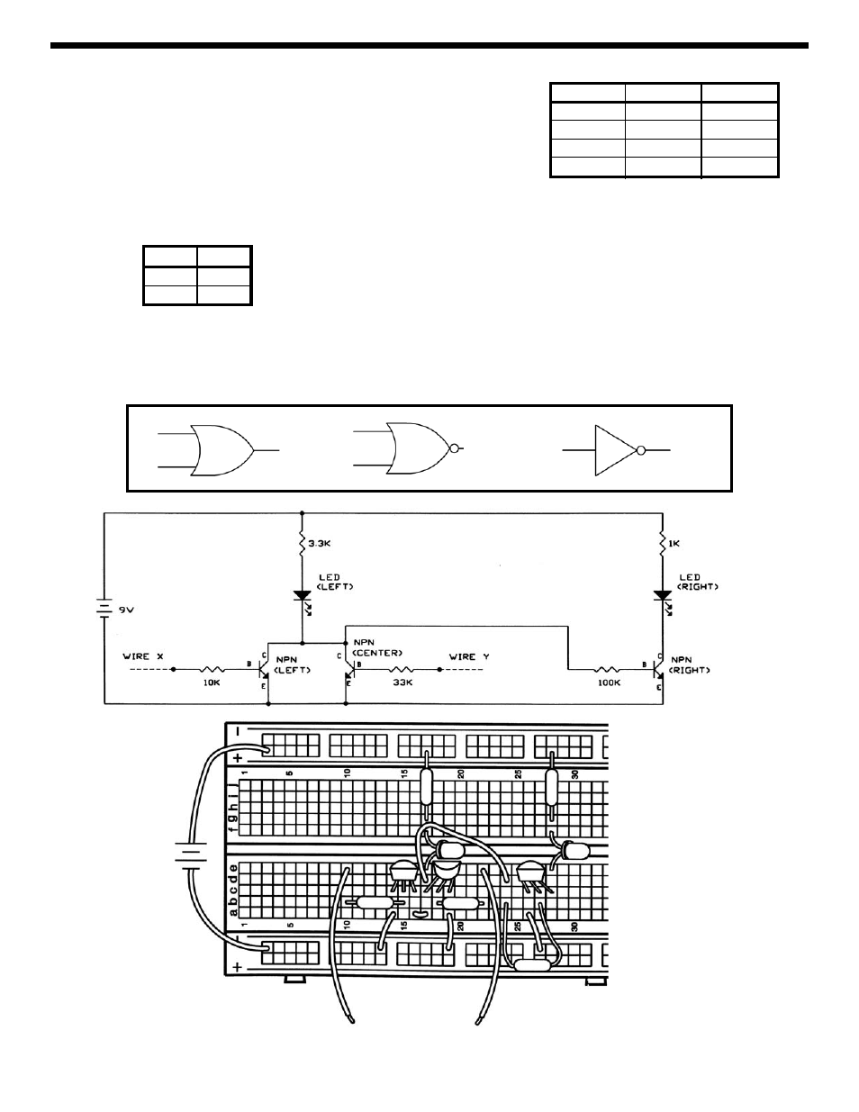
Now let’s add on to the previous circuit. Everything from Experiment 46
remains in place, just add the new parts and wires shown in the schematic and
Wiring Diagram. Test the four combinations of X and Y as before to determine
the state of LED-right (ON or OFF), filling in the table at right:
This table shows that if neither X
nor Y is HIGH then LED-right is ON. Hence, this configuration is called a NOR gate. X
and Y might represent your burglar alarm and flood detector, so if neither X nor Y is on then your “all clear” light goes on.
You may also think of this as adding a NOT gate to an OR gate to produce a NOR gate. A NOT gate is just the opposite
of its input:
Gates such as OR, NOR, and NOT form some of the basic building blocks for computers. The combinations of resistors
and transistors shown here to build them are a form of Resistor-Transistor-Logic, which was used extensively in early
generations of computers and which led to the development of many of today’s logic families. These basic gates are so
commonly used that they have their own symbols:
X Y
LED-right
LOW LOW
LOW HIGH
HIGH LOW
HIGH HIGH
Input
NOT
LOW
HIGH
HIGH
LOW
OR Gate
NOR Gate
NOT Gate
+9V
3.3k
Ω
33k
Ω
10k
Ω
WIRE X
WIRE Y
1k
Ω
100k
Ω