Experiment #3: resistors in series – Elenco Basic Electronic Experiments User Manual
Page 13
EXPERIMENT #3: RESISTORS IN SERIES
Remove the resistors used in Experiment #2; the other parts are used here. Insert the new parts according to the Wiring
Checklist and press the switch. The LED is on but is very dim (this will be easier to see if you wrap your hand near the
LED to keep the room lights from shining on it). Take a look at the schematic. There is a low 3.3k
Ω resistor and a high
100k
Ω resistor in series (one after another). Since the LED is dimly lit, we know that the larger 100kΩ must be controlling
the current. You can think of this as where two sections of the pipe are filled with rock, if one section is much longer than
the other then it controls the water flow. If you had several rock sections of different lengths then it is easy to see that these
would add together as if they were one longer section. The total length is what matters, not how many sections the rock
is split into. The same is true in electronics - resistors in series add together to increase the total resistance for the
circuit. (In our circuit the 3.3k
Ω and 100kΩ resistors add up to 103.3kΩ).
To demonstrate this, remove the 100k
Ω resistor and insert the 10kΩ in the same holes, press the switch; the LED should
be easy to see now (total resistance is now only 13.3k
Ω). Next, remove the 10kΩ resistor and replace it with the 1kΩ. The
LED is now bright, but not as bright as when you used the 1k
Ω in Experiment #1. Why? Because now the 3.3kΩ is the
larger resistor (total resistance is 4.3k
Ω).
Also, in Experiment #2 you saw how the 1k
Ω resistor would dominate the circuit when the variable resistor was set for 0Ω
and how the variable resistor would dominate when set for 50k
Ω.
Parts Needed:
• a 9V battery or power supply
• Switch
• one 1k
Ω resistor (brown-black-red-gold)
• one 3.3k
Ω resistor (orange-orange-red-gold)
• one 10k
Ω resistor (brown-black-orange-gold)
• one 100k
Ω resistor (brown-black-yellow-gold)
• one LED
• 1 wire
Wiring Checklist ( indicates same position as
last experiment):
Insert red battery wire or positive power supply into
hole j4 and black battery wire or negative power
supply (ground) into hole (–)3.
Insert switch into holes f4 and f5.
Insert the LED into holes g20 and g21 (“flat” side
goes into g21).
Insert a short wire between holes f21 and (–)21.
Insert the 3.3k
Ω resistor into holes i5 and i12.
Insert the 100k
Ω resistor into holes j12 and j20
(avoid touching other components).
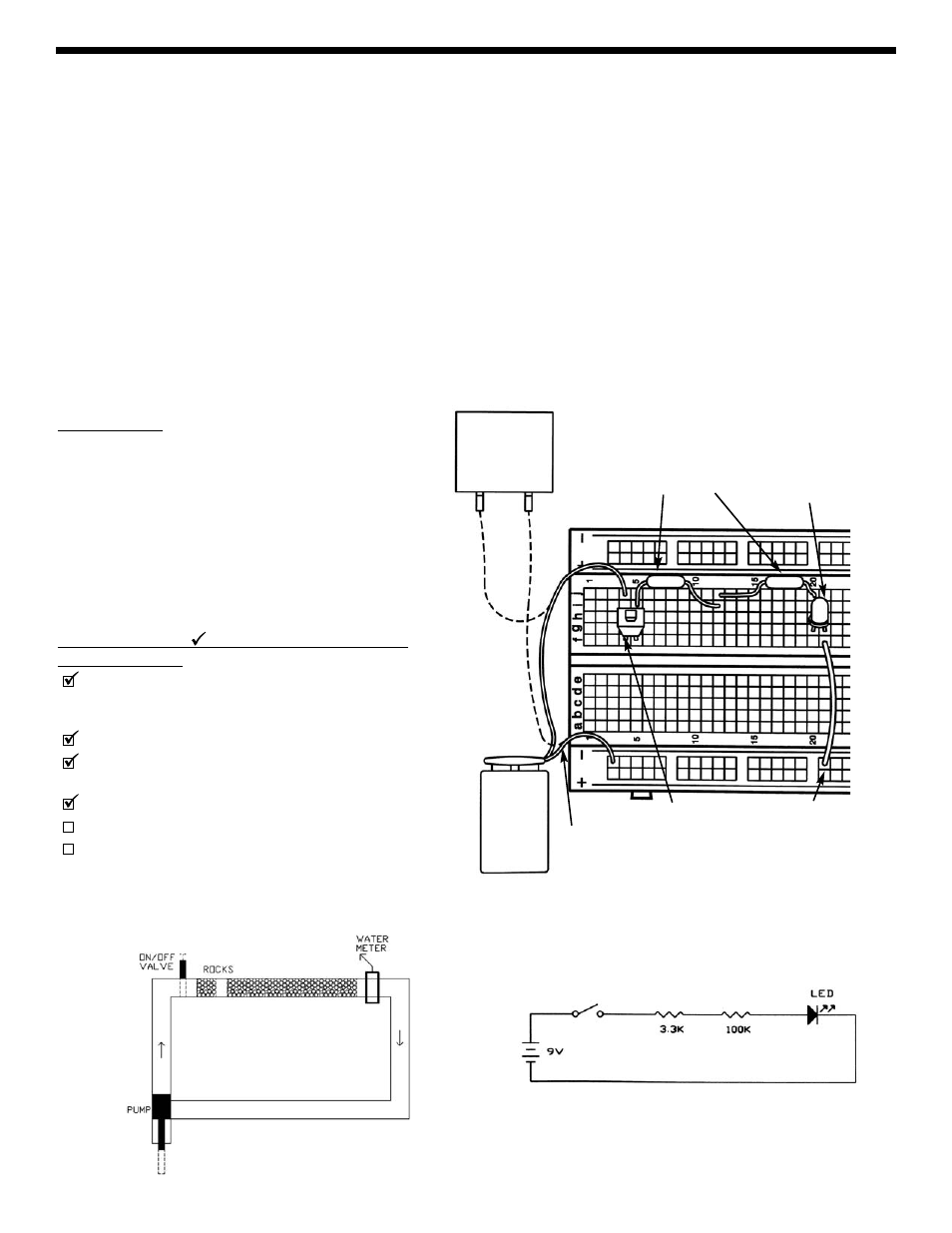
SCHEMATIC
WATER DIAGRAM
9V
BATTERY
POWER
SUPPLY
+9V
0V
(BLACK)
(RED)
3.3k
Ω
RESISTORS
LED
(symbol shows flat
side is on right)
SWITCH
WIRE
WIRING DIAGRAM
100k
Ω
13