Experiment #46: this or that – Elenco Basic Electronic Experiments User Manual
Page 63
63
EXPERIMENT #46: THIS OR THAT
Now that you’re familiar with the flip-flop, let’s introduce some more digital circuits. Digital circuits are circuits that have only
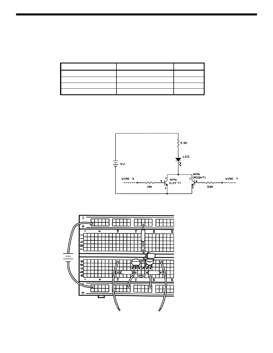
two states, such as high-voltage/low-voltage, on/off, yes/no, and true/false. Connect the circuit. Take a look at the
schematic, it is very simple. Wires X and Y are considered to be digital inputs, so connect them to either the (+) row of
holes (9V, or HIGH) or leave them unconnected (this is the same as connecting them to 0V, or LOW). Test the four
combinations of X and Y to determine the state of the LED (ON or OFF), filling in the table below:
X
Y
LED
LOW/UNCONNECTED
LOW/UNCONNECTED
LOW/UNCONNECTED
HIGH/9V
HIGH/9V
LOW/UNCONNECTED
HIGH/9V
HIGH/9V
This type of table is called a truth table. From it, you can see that if X
or Y is HIGH then the LED will be ON. Hence, this
configuration is called an OR gate. X and Y might represent two switches to turn on a light in your house. Or they might
represent sensors at a railroad crossing; if either senses a train coming they start the ding-ding sound and lower the gate.
You could also have more than two inputs, by adding more parts to your circuit and more columns to the truth table.
+9V
3.3k
Ω
33k
Ω
10k
Ω
WIRE X
WIRE Y