Experiment #7: water detector – Elenco Basic Electronic Experiments User Manual
Page 17
17
EXPERIMENT #7: WATER DETECTOR
You’ve seen how electricity flows through copper wires easily and how carbon resists the flow. How well does water pass
electricity? Let’s find out.
Connect the parts and wires according to the Wiring Checklist and take a look at the schematic. There isn’t a switch this
time, so just disconnect one of the wires if you want to turn the circuit off. Notice that the Wiring Checklist leaves 2 wires
unconnected. The LED will be off initially (if you touch the two loose wires together then it will be on). Now take a small
cup (make sure it isn’t made of metal), fill it half way with water, and place the two unconnected wires into the water without
touching each other. The LED should now be dimly lit, but the brightness could vary depending on your local water quality.
You are now seeing a demonstration of how water conducts (passes) electricity. (A small cup of water like this may be
around 100k
Ω, but depends on the local water quality). Try adding more water to the cup and see if the LED brightness
changes (it should get brighter because we are “making the water pipe larger”). Since the LED only lights when it is in
water now, you could use this circuit as a water detector!
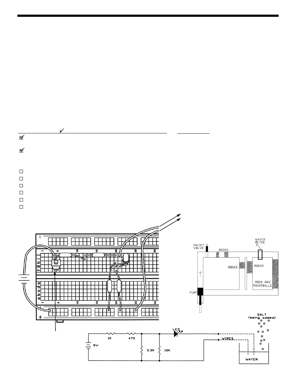
Now adjust the amount of water so that the LED is dimly lit. Now, watching the LED brightness, add some table salt to the
water and stir to dissolve the salt. The LED should become brighter because water has a lower electrical resistance when
salt is dissolved in it. Looking at the water pipe diagram, you can think of this as a strong cleaner dissolving paintballs that
are mixed in with the rocks. You could even use this circuit to detect salt water like in the ocean!
Parts Needed:
a 9V battery or power supply
one 470
Ω resistor (yellow-violet-brown-gold)
one 1k
Ω resistor (brown-black-red-gold)
one 3.3k
Ω resistor (orange-orange-red-gold)
one 10k
Ω resistor (brown-black-orange-gold)
one LED
2 long wires
a glass of water and salt
+9V
1k
Ω
470
Ω
Wiring Checklist ( indicates same position as last experiment):
Insert red battery wire or positive P. S. into j4 and black battery wire
or negative P. S. (ground) into (–)3.
Insert an LED into g20 and g21 (“flat” side goes into g21).
Note:
Keep the switch in the breadboard (unconnected) until later
experiments, as it can be difficult to remove and insert.
Insert the 470
Ω resistor into j12 and j20.
Insert the 1k
Ω resistor into i4 and i12.
Insert the 3.3k
Ω resistor into h20 and (–)18.
Insert the 10k
Ω resistor into f20 and (–)21.
Insert a long wire into j21 (the other end is unconnected for now).
Insert a long wire into (–)25 (the other end is unconnected for now).
10k
Ω
3.3k
Ω
TO GLASS
OF WATER
Note: Switch is not
used here but leave
in for future
experiments.