Experiment #2: the brightness control – Elenco Basic Electronic Experiments User Manual
Page 12
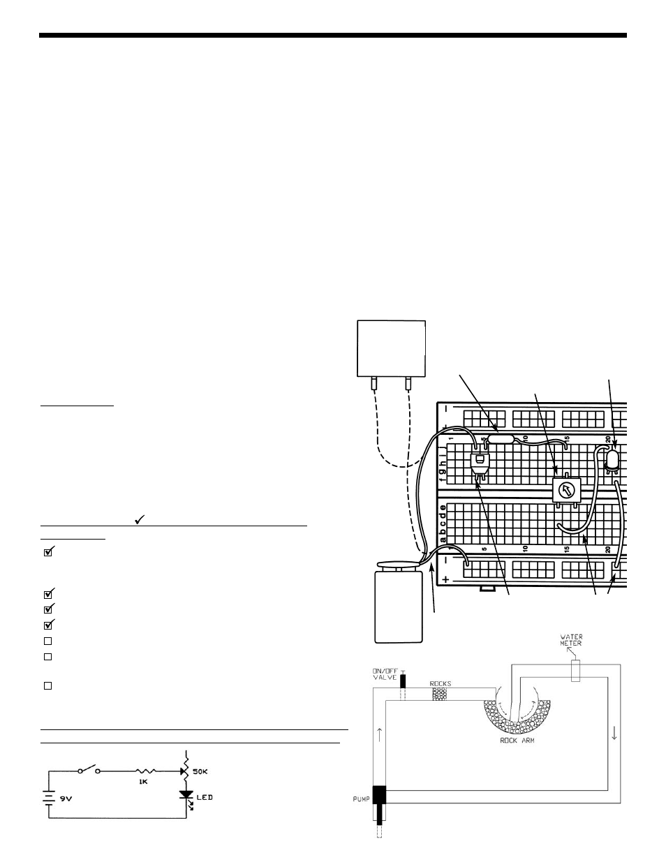
WATER DIAGRAM
EXPERIMENT #2: THE BRIGHTNESS CONTROL
Remove the 10k
Ω resistor used in Experiment #1; the other parts are used here. Insert the new parts according to the
Wiring Checklist below. Press the switch and the LED lights up (it may be dim). Now hold the switch closed with one hand
and turn the dial on the variable resistor with the other. When the dial is turned to the left, the resistance in the circuit is
low and the LED is bright because a large current flows. As you turn the dial to the right the resistance increases and the
LED will become dim, just as forcing the water through a section of rocks would slow the water flow and lower the reading
on your water meter.
You may be wondering what the 1k
Ω resistor is doing in the circuit. If you set the dial on the variable resistor for minimum
resistance (0
Ω) then Ohm’s Law tells us the current will be very large - and it might damage the LED (think of this as a
very powerful water pump overloading a water meter). So the 1k
Ω was put in to limit the current while having little effect
on the brightness of the LED.
Now remove the wire from c14 and connect it to c16. Do you know what will happen now? Close the switch and you will
see that as you turn the dial from the left to the right the LED goes from very dim to very bright (the opposite of when
connected to c14), because you are decreasing the resistance between the center and right pins.
Now remove the 1k
Ω resistor from hole j15 and insert it into hole c14 (the other end stays in j5). What do you think will
happen? Close the switch and turn the dial on the variable resistor. The LED is dim and turning the resistor dial won’t
make it any brighter. As discussed above, the resistance between the left and right pins is always 50k
Ω and the part acts
just like one of the other resistors in your PK-101.
SCHEMATIC
Variable resistors like this one are used in the light dimmers you
may have in your house, and are also used to control the volume
in your radio, your TV, and many electronic devices.
Parts Needed:
• a 9V battery or power supply
• Switch
• one 1k
Ω resistor (marked brown-black-red-gold)
• 50k
Ω variable resistor
• one LED
• 2 wires
Wiring Checklist ( indicates same position as last
experiment):
Insert red battery wire or positive power supply into hole j4
and black battery wire or negative power supply (ground) into
hole (–)3.
Insert switch into holes f4 and f5.
Insert the LED into holes g20 and g21 (“flat” side goes into g21).
Insert a short wire between holes f21 and (–)21.
Insert the 1k
Ω resistor into holes j5 and j15.
Insert the 50k
Ω variable resistor into holes e14, g15, and e16.
It may be a tight fit, carefully press it in slowly.
Insert a short wire between holes c14 and j20.
Be sure all your wires are securely in place and not loose. Also
make sure the metal into each hole is not touching any
other metal, including other parts of the same component.
9V
BATTERY
POWER
SUPPLY
+9V
0V
(BLACK)
(RED)
1k
Ω
RESISTOR
LED
(symbol shows
flat side is on
right)
SWITCH
WIRES
WIRING DIAGRAM
50k
Ω
VARIABLE
RESISTOR
12