SINGER 201 User Manual
Page 27
Attention! The text in this document has been recognized automatically. To view the original document, you can use the "Original mode".
Should it become necessary to remove
and disassemble the tension, proceed as
follows:
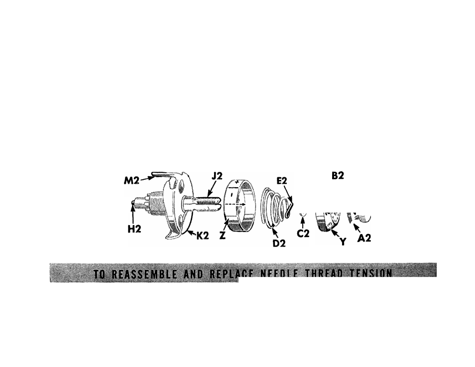
Turn thumb nut A2, Fig. 2 7 over
toward the left until it stops at “0”
on numbered dial Y. Press in dial to dis
engage pin B2 in thumb nut and remove
thumb nut. Then remove tension parts
from stud J2 as shown below. To
remove pin H2 from stud J2, remove
face plate from machine and tilt ma
chine so that the pin will drop out. Do
not remove stud J2. (It is shown re
moved in Fig. 2 7, only for the purpose
of illustration.)
4$- —
I
Fig.
27.
Needle Thread Tension Disassembled
See Fig. 27
tension discs on stud, having the flat.
Replace face plate, insert tension re- thread-bearing sides of discs together,
leasing pin H2 in stud. Place the two Place thread guard plate K2 on stud,
26