A caution, Fig. 27 — condenser fan adjustment – Carrier 09DK054-084 User Manual
Page 29
Attention! The text in this document has been recognized automatically. To view the original document, you can use the "Original mode".
START-UP
System Evacuation and Dehydration
— Refer
to GTAC II, Module 4, “Dehydration for Proper Evacua
tion and Dehydration techniques.”
Charging Procedure
— Charge to a clear sight glass.
Refer to GTAC II, Module 5 “Charging, Recovery, Recy
cling, and Reclamation” for proper charging techniques.
Add 10 lbs (4.5 kg) of R-22 over clear sight glass to flood
subcooler sections of the condenser coils. This 10 lbs
(4.5 kg) is added to the total unit charge, and must be pro
portioned by the percentage of circuits when multiple cir
cuits are employed. For example, in Table 2, add .67 x
10 lbs (4.5 kg) (approximately 6.7 lbs [3.0 kg]) for the 67%
circuit. Refer to Table 6 for condenser coil refrigerant
circuit data.
Check Operation of Condenser Fan Motor Con
trols and Rotation of Fans —
Rotation should be
clockwise as viewed from top of unit.
A
CAUTION
Before starting unit, be sure wire fan guards are
secured in place over each fan; personal injury may
result.
SERVICE
Cleaning Condenser Coils
— Clean coils with a vac
uum cleaner, fresh water, compressed air, or a bristle brush
(not wire). Units installed in corrosive environments should
have coil cleaning as a part of a planned maintenance sched
ule. In this type of application, all accumulations of dirt
should be cleaned off the coil.
A
CAUTION
Do not use high-pressure water or air. Damage to fins
may result.
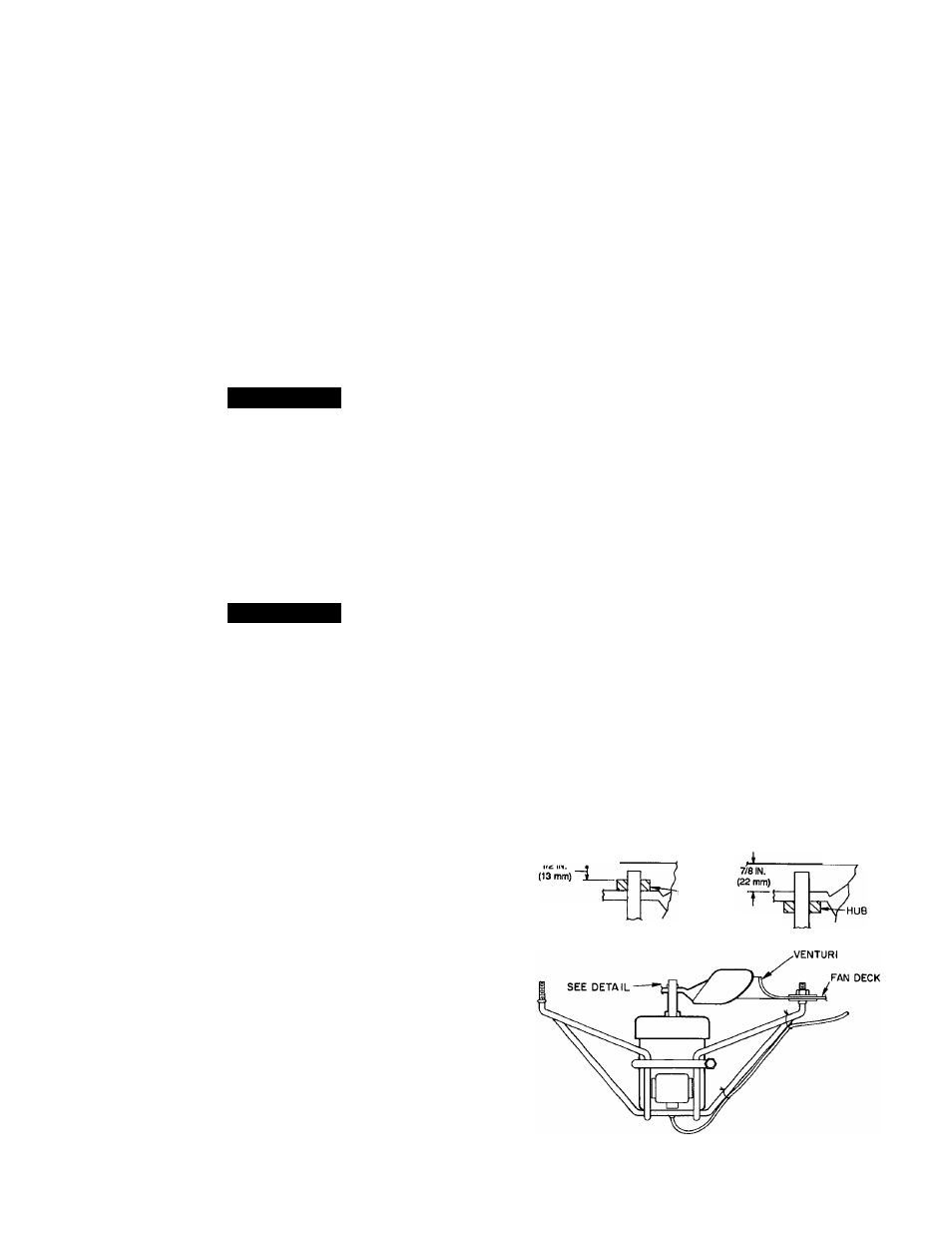
Condenser Fans
— Each fan is supported by a formed
wire mount bolted to the fan deck and covered with a wire
guard. The exposed end of the fan motor shaft is protected
by grease. If the fan motor must be removed for service or re
placement, be sure to grease fan shaft, and reinstall fan guard.
For proper performance, fan should be 7/8 in. (22 mm) be
low the top of the venturi on the fan deck for 60 Hz units,
and 1/2 in. (13 mm) to top of the fan hub for 50 Hz units.
Tighten set screws to 15 ± 1 ft-lbs (20 ± 1 . 3 N-m). Fig
ure 27 shows the proper position of the mounted fan.
IMPORTANT: Check for proper fan rotation (clock
wise viewed from above). If rotation needs to be re
versed on one motor, disconnect main power supply
and switch motor leads at the fan contactor. If rota
tion needs to be reversed on all motors, disconnect
main power supply and switch two leads at TBl.
Lubrication
— Fan motors have permanently lubricated
bearings.
Head Pressure Control
— Reduce condensing capac
ity under low ambient temperature conditions. See Fan
Cycling section below.
FAN CYCLING — Efficient operation of evaporator ther
mostatic expansion valves require a 90 F (32 C) minimum
saturated condensing temperature when compressors are op
erating at 100% capacity, 80 F (27 C) for 75% compressor
capacity, and 70 F (21 C) for 50 and 25% compressor
capacity.
The capacity of an air-cooled condenser increases with
increased temperature difference (defined as entering satu
rated condenser temperature minus entering outdoor-air tem
perature) and decreases with decreased temperature differ
ence. A drop in entering outdoor-air temperature results in
a lower saturated condensing temperature. When outdoor-
air temperature drops below the minimum temperatures listed
in Table 7 for standard units, additional head pressure con
trol is required.
Model 09DK units have fully automatic intermediate-
season head pressure control through condenser fan cycling
using electromechanical fan cycling controls. Standard head
pressure controls will control the 100 and 50/50% con
denser capacity applications. Head pressure can also be con
trolled by fan cycling controls supplemented by the acces
sory Motormaster® III solid-state head pressure controller.
See Motormaster III installation instructions for more infor
mation. Other circuit split applications (67/33, 33/33/33,
33/33/17/17% capacity splits) will require the accessory fan
control kit which includes a control panel and additional
fan cycling pressure switches. See fan control installation
instructions for more information.
In the standard control scheme, fans 1 and 2 will be on
when there is a call for cooling from the respective coil cir
cuits. Fans 1 and 2 are non-cycling. On 054 and 064 units,
fans 3 and 4 will be controlled by using a fan cycling pres
sure switch on each of the primary coil circuits in response
to condensing pressure. On 074 and 084 units, fans 3 and 4
will also be controlled using a fan cycling pressure switch
in each of the primary coil circuits in response to condens
ing pressure. Fans 5 and 6 will be controlled by using two
air temperature switches, which respond to the outdoor am
bient temperature. The air temperature switches are located
on the control box shelf. For temperature and pressure set
ting details, see Table 8.
With respect to the fan cycling pressure switch control,
fans 3 and 4 are on above 260 ± 15 psig (1793 ± 103 kPa)
and off below 160 ± 10 psig (1103 ± 69 kPa). If pressure
is rising between 160 psig (1103 kPa) and 260 psig
(1793 kPa), fans 3 and 4 are off. If pressure is reducing
from 260 psig (1793 kPa) to 160 psig (1103 kPa) fans 3 and
4 are on. With respect to the air temperature switch control
on the 074 and 084 condensers, below 70 ± 3° F
(21.1 ± 1.7° C) outdoor ambient, fans 5 and 6 are off; above
80 ± 3° F (26.7 ± 1.7° C) fans 5 and 6 are on. Between
70 F (21.1 C) and 80 F, (26.7 C) whether fans 5 and 6 are
on or off depends on whether temperature is rising or fall
ing. If the temperature is rising from 70 F (21.1 C) to 80 F
(26.7 C), fans 5 and 6 are off. If the temperature is falling
from 80 F (26.7 C) to 70 F (21.1 C), fans 5 and 6 are on.
TOP OF VENTURI
ON FAN DECK
TOP OF VENTURI
ON FAN DECK
L
HUB
ALL 50-Hz
UNITS
ALL 60-Hz
UNITS
29
NOTE: Fan rotation is ciockwise as viewed from top of unit
Fig. 27 — Condenser Fan Adjustment