O o o 0 – Carrier 09DK054-084 User Manual
Page 19
Attention! The text in this document has been recognized automatically. To view the original document, you can use the "Original mode".
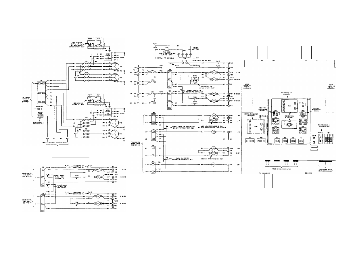
09DK05^.054 POWER SCHEMATIC
09D
k
:054.064
standard
control
schematic
nOO% 8 50X/50X CAPACITY SPLITS)
ir
FW CONTROI. (IT IS USED. SEE FW CONTRa CIt (tCCESSOAri SOOUTIC
09DIC054.064 FAN CONTROL KIT CACCESSOftYJ SCHEMATIC
C67X/33X.33X/33X/33X g 33X/33X/17X/17% CAPACITY SPLITS)
o
09PK054.064 COMPONENT ARRANGEMENT
&
cui
&
cSl
M
2
№1
0
0
0
U
2
Ml
(D>®®
®®<
32
)
2
oO
o
o
o>
o
l2Xi CDNIML VCL1ACE Oi«.r>
NOTES.
1
dXJKD
Units are factory wired for a 50%/50% capacity split. If 100% capacity is required, con
nect the factory-supplied jumpers from TB2-1 to TB3-1 and from TB2-2 to TB3-2.
2. When a fan control kit is used, the jumper from TB2-1 to TB3-1 and from TB2-2 to TB3-2
must be connected. The fan control kit is factory wired for 67%/33% capacity split. If a
33%/33%/33% capacity split is required, remove the jumper from TB4-1 to TB5-1 and
from TB4-2 to TB5-2. If a 33%/33%h 7%/17% capacity split is required, remove the jump
ers from TB4-1 to TB5-1 to TB7-1 and from TB4-2 to TB5-2 to TB7-2.
3. On fan control kits, 208/230 v units are factory wired for 230 v power supply. For 208 v
power supply, connect yellow wire to terminal marked H2.
4. Terminal blocks TB2, TB3, TB4, TBS, TB6 and TB7 are for external field control connec
tions. Control connections are to be class 1 wiring, 14 AWG copper conductors only.
5. Wiring for field power supply must be rated 75° C minimum. Use copper, copper-clad
aluminum, or aluminum conductors. Maximum incoming wire size for each terminal block
IS 2/0.
6. Replacement of factory wires must be with 105° C wire or its equivalent.
7. Factory wiring is in accordance with National Electrical Code (NEC). Field modifications
or additions must be in compliance with all applicable codes.
8. Fan motors are thermally protected. Three-phase motors are protected against primary
single phasing conditions.
9. Line numbers on the left side of the label diagrams indicate the contact number. The
numbers on the right side of label diagrams match the contacts with their corresponding
coils. A plain number indicates normally open contacts. An underlined number indicates
normally closed contacts.
Fig. 14 — Wiring Diagram and Component Arrangement; 054 and 064 Units
O o
o 0
CONTRCC RELIT
outrr TERnlNii.
’ EOUIRHENT
FAN COKTACIOA
FAN CTCLINC FRESSURE S
FACJ9ST INSIALLEB »Hi
NOIOfi NASTER SENSOR
PRINAftr
SCCCMOAAT
TERNiNAL eiOCi:
TRV6FCFUCR
r~l TERNINAL 8L0CC CC»»«C1ICN
O "*»F£D TERNINAl
O LMURCED TERnlNAL
□= C